RGB Mechanical 75% KEEB
This is my custom made rgb mechanical keyboard
Created by
 AlDeep
Tier 3
42 views
0 followers
 tap
requested changes for RGB Mechanical 75% KEEB ago
tap
requested changes for RGB Mechanical 75% KEEB ago
Really well made! But can you add explanation on how you made your cad model? Except this everything looks great!
AlDeep
submitted RGB Mechanical 75% KEEB for ship review ago
 Iamalive 🚀
requested changes for RGB Mechanical 75% KEEB ago
Iamalive 🚀
requested changes for RGB Mechanical 75% KEEB ago
Thanks for adding the step files, but can you add at least a little explanation on how you made your cad model? Right now there's no screenshots of the in-between, just that it's done. Other than that, this looks really clean! Thanks!
AlDeep
submitted RGB Mechanical 75% KEEB for ship review ago
 Tanuki ⚡🚀
requested changes for RGB Mechanical 75% KEEB ago
Tanuki ⚡🚀
requested changes for RGB Mechanical 75% KEEB ago
Hey! I LOVE your journalling, however, please journal more on the actual case! I just see the end product :P Please include .step as well! I think it could be more polished, I think you could add mounting as well! I do love the documentation on the PCBs, and the actual PCB does look very very polished!
AlDeep
submitted RGB Mechanical 75% KEEB for ship review ago
 PenguinMo
requested changes for RGB Mechanical 75% KEEB ago
PenguinMo
requested changes for RGB Mechanical 75% KEEB ago
Wow this looks cool but is there anyway to reduce the price try looking on aliexpress things are usually cheaper over there I know you said you are but from the look of your screenshots it seems that you are still using amazon
AlDeep
submitted RGB Mechanical 75% KEEB for ship review ago
PenguinMo
requested changes for RGB Mechanical 75% KEEB ago
Wow this looks cool but is there anyway to reduce the price try looking on aliexpress things are usually cheaper over there
AlDeep
submitted RGB Mechanical 75% KEEB for ship review ago
Iamalive 🚀
requested changes for RGB Mechanical 75% KEEB ago
Please full read the repo readme instructions on https://blueprint.hackclub.com/about/submission-guidelines. Additionally, try looking for the parts you're getting off of amazon on other retail sites like Aliepxress or temu, as those are much cheaper!
AlDeep
submitted RGB Mechanical 75% KEEB for ship review ago
 technical_.
requested changes for RGB Mechanical 75% KEEB ago
technical_.
requested changes for RGB Mechanical 75% KEEB ago
There should be some code to validate that your PCB works!
In addition, make sure you have accounted for shipping and tariffs.
AlDeep
submitted RGB Mechanical 75% KEEB for ship review ago
technical_.
requested changes for RGB Mechanical 75% KEEB ago
Your cart only shows ~12 dollars. Please add cart screenshots, or update the grant amount you are requesting. Cart images should show the full cart.
AlDeep
submitted RGB Mechanical 75% KEEB for ship review ago
 Shaurya Bisht
requested changes for RGB Mechanical 75% KEEB ago
Shaurya Bisht
requested changes for RGB Mechanical 75% KEEB ago
need images of the pcb and scehmatic, also you have loose files like kicad files that should be organized into folders.
AlDeep
submitted RGB Mechanical 75% KEEB for ship review ago
Iamalive 🚀
requested changes for RGB Mechanical 75% KEEB ago
You need to have a seperate BOM.csv and also add the full cart screenshot for the parts! Only the price of the pcb is shown right now :(
AlDeep
submitted RGB Mechanical 75% KEEB for ship review ago
AlDeep
added to the journal ago
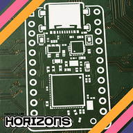
Keyboard Case
At the end i added my signiture on the front silkscreen and exported the pcb.

This was easy task i am good in CAD so i made a simple flat case no fancy things i made it in Fusion360 and got it done then i rendered the images with the exported PCB.


AlDeep
added to the journal ago
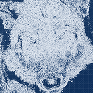
MCU Connections
I think the image speaks for itself, yes i had to do that and do cross overs which was crazy as somehow the pins where not in correct order for the matrix cols and rows so had to put a lot of vias in order to get it done.

AlDeep
added to the journal ago
LEDs
This was the most tiring phase because i realized i was using the wrong led footprint so i had to change the schematic symbol and added the SK mini e reverse mount version of led so i can put it anywhere as it doesn't interfere with the upper layer.
Then i had to place every led in its place below the 3 pin holes and then i started connecting each single power pin to a main +5v power line and repeat that every single led, then i made the same changes again for the ground pins and then try to figure out how to connect the other two (DIN-DOUT) signal pins
so i worked on the inner layers of the board and connect every SINGLE LED which was absolute pain, but at the end i got it all together.


AlDeep
added to the journal ago
PCB & Layout
Schematic addition
I have added additional parts in schematic which are the stabilizers.

I have changed the leds footprint to the SK mini which are much smaller in size from the main mini.
PCB Auto Layout
I pulled all components then used the kbplacer plugin for layout, it auto connected some of the columns and rows so i had few left unconnected to connect then i placed the stabalizers according to their sizes.
This process took some time as i had multiple issues when auto placing LEDs using the plugin, for some reason the plugin was not capable of doing it so i had to remove the leds then pull them back after auto placement.

MCU
The microcontroller was connected to the USB-C from a preloaded template.
AlDeep
added to the journal ago
Keyboard Keys Schematic
Keys
To start making the key matrix i open a new sheet and i started putting down the 45 angled switch key and the diode, then i copied the same thing for the total number of keys, then i connected the matrix for columns and rows and added the global labels, to finish with the exact number of keys i removed additional ones in the matrix leaving space for shift and spacebar and other keys making the schematic ready to pull into the pcb editor.

Here is the final result in the main schematic sheet with the global labels

LEDs
For the addressable RGB leds i use the SK6812, i got the 84 leds for each key on the layout, with that i started connecting them in series, and gave global label for the converted power coming from the MCU.

LED Power Converter
In order to have stable signal coming from the MCU and flowing to the final led without degradation of signal i convert the 3.3v to 5v for the Signal lines, using the 74LVCH2T45DC and connecting in as the following.

Rotary Encoder
I have added this rotary encoder gave it a traditional connection i found on a tutorial, i am going to change the labels for the matrix.

Schematic Polishing
Making titles and box areas for each part.

AlDeep
added to the journal ago
First hands on Schematic
MCU
Controller Chip
For the chip i chose a common chip which is the STM32F072CBT6 is has many GPIOs, i am not sure if it would take everything i need but until now it should work.
I have started giving out labels to the pins just regular names and connected ground pins to ground

Decoupling Caps
In decoupling capacitors area i followed the general guides and made very standard connections.

Boot button
Made a bootloader button circuit.

Power Supply
USB-C port
Here i am connecting ground then the data differentials and following standard connection for CC1 and CC2 by pulling them to ground and for vbus i am connecting fuse for current limit

Static Elect.. Protection
ESD protection circuit, connected from the USB then to the chip for static electricity protection.

Voltage stepdown
Finally i made voltage stepdown from USB to 3.3v.

Misc
At the end i added mounting holes for the keyboard, i stick with 4 holes as i think the keyboard is compact enough for those.

AlDeep
added to the journal ago
Building an Idea
I open keyboard layout editor to start choosing a layout, i chose the one in the image below and i also want to have a rotary encoder.

As shown it is a 75% keyboard, i am planning to have a rotary encoder maybe multiple ones.

I have calculated the numbers for the matrix rows / columns which is 6 rows, 15 column making 84 Keys in Total.
AlDeep
started RGB Mechanical 75% KEEB ago
11/24/2025 - Building an Idea
I open keyboard layout editor to start choosing a layout, i chose the one in the image below and i also want to have a rotary encoder.
As shown it is a 75% keyboard, i am planning to have a rotary encoder maybe multiple ones.
I have calculated the numbers for the matrix rows / columns which is 6 rows, 15 column making 84 Keys in Total.
11/25/2025 - First hands on Schematic
MCU
Controller Chip
For the chip i chose a common chip which is the STM32F072CBT6 is has many GPIOs, i am not sure if it would take everything i need but until now it should work.
I have started giving out labels to the pins just regular names and connected ground pins to ground
Decoupling Caps
In decoupling capacitors area i followed the general guides and made very standard connections.
Boot button
Made a bootloader button circuit.
Power Supply
USB-C port
Here i am connecting ground then the data differentials and following standard connection for CC1 and CC2 by pulling them to ground and for vbus i am connecting fuse for current limit
Static Elect.. Protection
ESD protection circuit, connected from the USB then to the chip for static electricity protection.
Voltage stepdown
Finally i made voltage stepdown from USB to 3.3v.
Misc
At the end i added mounting holes for the keyboard, i stick with 4 holes as i think the keyboard is compact enough for those.
11/26/2025 - Keyboard Keys Schematic
Keys
To start making the key matrix i open a new sheet and i started putting down the 45 angled switch key and the diode, then i copied the same thing for the total number of keys, then i connected the matrix for columns and rows and added the global labels, to finish with the exact number of keys i removed additional ones in the matrix leaving space for shift and spacebar and other keys making the schematic ready to pull into the pcb editor.
Here is the final result in the main schematic sheet with the global labels
LEDs
For the addressable RGB leds i use the SK6812, i got the 84 leds for each key on the layout, with that i started connecting them in series, and gave global label for the converted power coming from the MCU.
LED Power Converter
In order to have stable signal coming from the MCU and flowing to the final led without degradation of signal i convert the 3.3v to 5v for the Signal lines, using the 74LVCH2T45DC and connecting in as the following.
Rotary Encoder
I have added this rotary encoder gave it a traditional connection i found on a tutorial, i am going to change the labels for the matrix.
Schematic Polishing
Making titles and box areas for each part.
11/28/2025 - PCB & Layout
Schematic addition
I have added additional parts in schematic which are the stabilizers.
I have changed the leds footprint to the SK mini which are much smaller in size from the main mini.
PCB Auto Layout
I pulled all components then used the kbplacer plugin for layout, it auto connected some of the columns and rows so i had few left unconnected to connect then i placed the stabalizers according to their sizes.
This process took some time as i had multiple issues when auto placing LEDs using the plugin, for some reason the plugin was not capable of doing it so i had to remove the leds then pull them back after auto placement.
MCU
The microcontroller was connected to the USB-C from a preloaded template.
12/4/2025 3 PM - LEDs
This was the most tiring phase because i realized i was using the wrong led footprint so i had to change the schematic symbol and added the SK mini e reverse mount version of led so i can put it anywhere as it doesn't interfere with the upper layer.
Then i had to place every led in its place below the 3 pin holes and then i started connecting each single power pin to a main +5v power line and repeat that every single led, then i made the same changes again for the ground pins and then try to figure out how to connect the other two (DIN-DOUT) signal pins
so i worked on the inner layers of the board and connect every SINGLE LED which was absolute pain, but at the end i got it all together.
12/4/2025 4:00 PM - MCU Connections
I think the image speaks for itself, yes i had to do that and do cross overs which was crazy as somehow the pins where not in correct order for the matrix cols and rows so had to put a lot of vias in order to get it done.
12/4/2025 4:03 PM - Keyboard Case
At the end i added my signiture on the front silkscreen and exported the pcb.
This was easy task i am good in CAD so i made a simple flat case no fancy things i made it in Fusion360 and got it done then i rendered the images with the exported PCB.