WaifuFC - Flight Controller
Just Flight Controller with STM32 change the tier if i set it low
Created by
 Jadamek1337
Tier 3
43 views
0 followers
Timeline
 CAN ⚡🚀
submitted WaifuFC - Flight Controller for review ago
CAN ⚡🚀
submitted WaifuFC - Flight Controller for review ago
Jadamek1337
submitted WaifuFC - Flight Controller for review ago
Jadamek1337
added to the journal ago
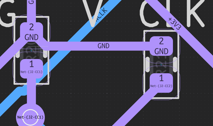
Adding Resistance Values to CC Resistors
In this additional step I added the resistor values for the two resistors going to GND from the USBC connector.
The entire project has been completed. It was supposed to be a blast, but it turned out to be very difficult and demanding.
 NotARoomba 🚀
requested changes for WaifuFC - Flight Controller ago
NotARoomba 🚀
requested changes for WaifuFC - Flight Controller ago
Please add in 5.1K resistors to ground on your CC pins in the USB-C connector or it will not give any voltage.
Jadamek1337
submitted WaifuFC - Flight Controller for review ago
Jadamek1337
added to the journal ago
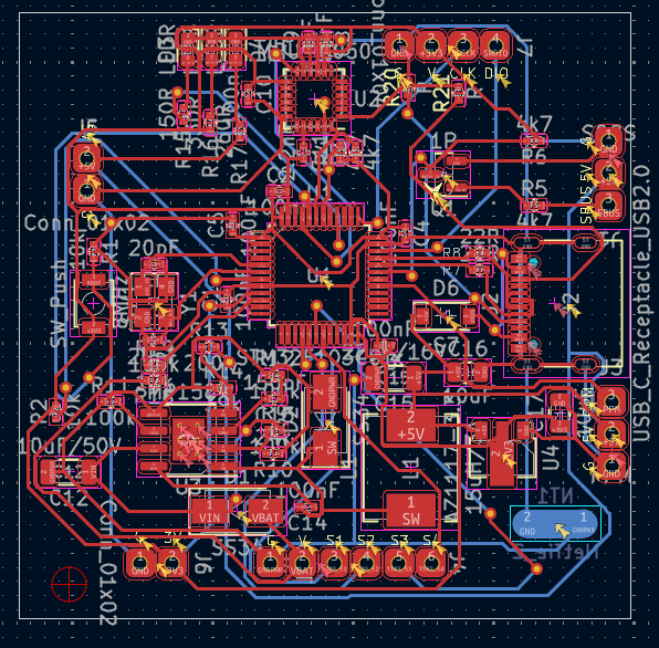
Final PCB Fix
I managed to fix most of the errors.
The remaining issues, such as violations of hole clearance and similar minor problems, honestly don’t interest me—just like vias. I’m not creating a microcontroller for an F-35, but for a drone, so these details don’t matter to me.
Overall, I didn’t follow the tutorial step by step; I started creating this project before the tutorial was released.
I was advised not to include a donation section if I don’t need money.
I consider the project finished.
NotARoomba 🚀
requested changes for WaifuFC - Flight Controller ago
You have various errors in the DRC of your board, please fix them!
Jadamek1337
submitted WaifuFC - Flight Controller for review ago
Jadamek1337
added to the journal ago
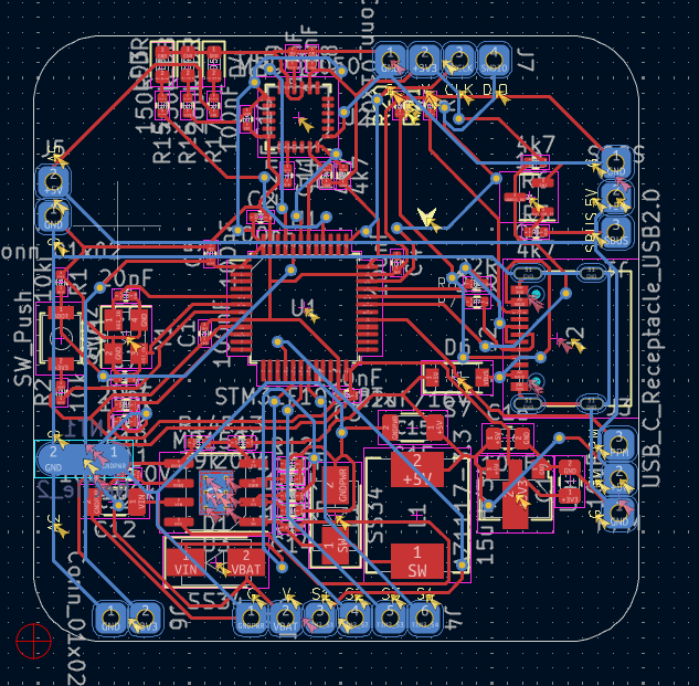
Improvements v2
Key Changes
- Impedance Matching: Adjusted the distance of critical cables, such as DP and DN, to achieve similar impedance and minimize interference.
- Via Reduction: Removed vias wherever possible. While complete elimination wasn't feasible, the number has been significantly reduced.
- Visual Improvements: Enhanced the overall appearance for better readability and aesthetics.
These changes aim to improve performance while maintaining a clean and professional PCB layout.
I think that's all it will take to fix anything, and it will work for me. I don't need a huge demand.
NotARoomba 🚀
requested changes for WaifuFC - Flight Controller ago
Looks good, but you need to make your USB-C DP and DN lines the same length (try not to use autorouter). And also a good rule of thumb is to never use more than 2 vias per trace for a 2 layer board. Check out this guide and scroll out to the "Layout" section: https://blueprint.hackclub.com/starter-projects/flightcontroller. It may help following some of the tips there. Also you need 5.1K resistors to ground on your CC pins in the USB-C connector or it will not give any voltage.
Jadamek1337
submitted WaifuFC - Flight Controller for review ago
Jadamek1337
added to the journal ago
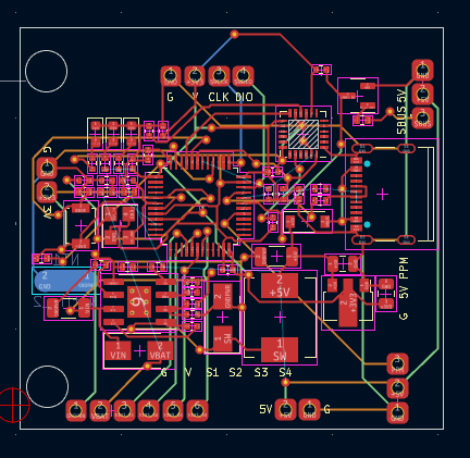
Fixed PCB
I repaired the PCB and reduced the number of layers from 4 to 2.
It was hell, but I managed to get everything done.
Additional Notes
- I had to re-route a significant portion of the board to fit everything onto two layers.
- Some traces required complete redesign due to space constraints.
- Despite the challenges, the final layout is cleaner and easier to manufacture.
- The experience gave me a much better understanding of layer optimization and signal routing.
Overall, it was a tough but valuable learning process.
NotARoomba 🚀
requested changes for WaifuFC - Flight Controller ago
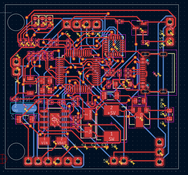
Your PCB has unconnected pads and also you can definitely make this board use only 2 layers.
Jadamek1337
submitted WaifuFC - Flight Controller for review ago
Jadamek1337
added to the journal ago
Troubleshooting and Fixes
During troubleshooting, I found a few issues, mainly related to incorrect routing, although I also discovered one mistake in the schematic. Fortunately, I managed to fix it.
This is unfortunately the last post, as there’s nothing more to do here—just an update for reviewers - I was also instructed not to include a parts basket image if I don’t need a grant.
I ignored these aesthetic flaws. I only care about performance.
Jadamek1337
added to the journal ago
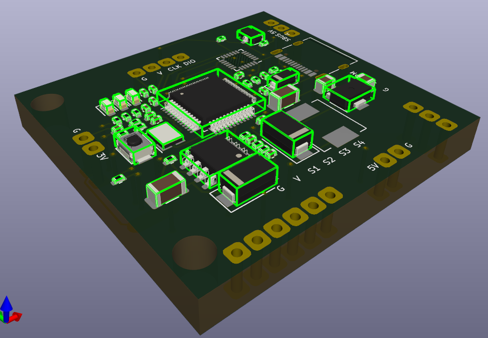
PCB Routing and Component Placement
In this almost final stage, I routed and placed all footprints on the PCB to ensure everything works.
It was quite challenging because I usually rely on autoroute, but in this case, since I didn’t want to risk mistakes, I did everything manually—and I have to say, I’m really proud of myself.
Now there’s just one step left: checking for errors and ordering the PCB.
 this is how it looks like :o
Jadamek1337
added to the journal ago
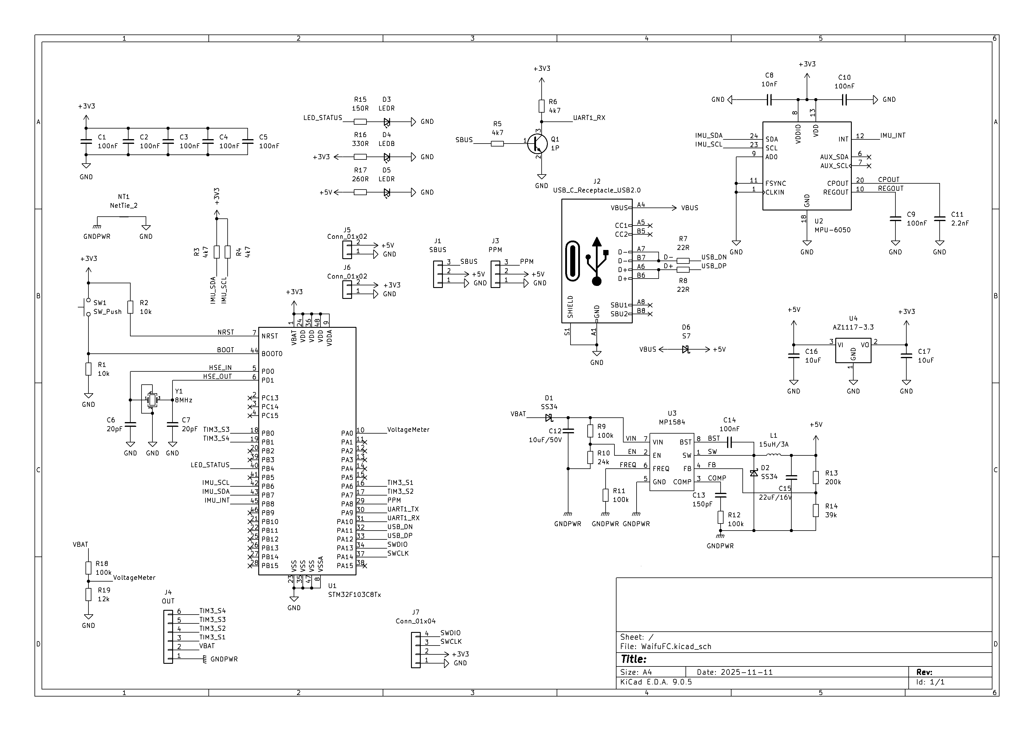
Schematic Creation
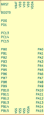
I created the full schematic. As I prefer not to waste time, I built a complete design, including understanding components such as the gyroscope and accelerometer, the pins on the microcontroller (e.g., ATmega), and how the new project structure will function.
Being a student in Automation Technology, PCB design and electronics are no problem for me (we even worked with complex numbers in the 2nd year, btw).
The schematic took me just a few hours to complete, but since I have limited time, I need to lock in the progress.
I focused on practical work and efficiency: the schematic is fully functional and ready for the next steps.
(For people who think it's fast and are beginners, it really doesn't work that way. I spent countless hours practicing other boards that were easier. Do the same and you'll master it.)
Jadamek1337
added to the journal ago
Understanding How the Flight Controller Works
At this stage, I focused on understanding the minimal set of components a flight controller needs to work:
| Component | Description |
|---|---|
| STM32F103C8T6 | Main microcontroller, handles all flight logic and communication |
| MPU-6050 | IMU sensor for measuring orientation and acceleration |
| MP1584 | Voltage regulator to provide stable supply voltage to the board |
| capacitors | Decoupling capacitors to stabilize the power supply to ICs |
| 8MHz crystal | Provides the clock signal for the microcontroller |
| SBUS connector | Receiver input for controlling the flight controller |
| USB-C connector | Interface for programming and telemetry |
As I prefer getting straight to the point, I didn’t focus much on unnecessary components and immediately started researching and creating the PCB and schematic.
I also apologize to the people who will be checking my work, but there is not much to say here... J*B!
Jadamek1337
started WaifuFC - Flight Controller ago