Pax the RP2040 Devboard
Learning PCB design using the Blueprint Custom Devboard tutorial!
Created by
 Voidless
Tier 3
6 views
0 followers
 CAN ⚡🚀
approved Pax the RP2040 Devboard ago
CAN ⚡🚀
approved Pax the RP2040 Devboard ago
Tier approved: 3
Grant approved: $51.00
Nice project
Voidless
submitted Pax the RP2040 Devboard for ship review ago
Voidless
added to the journal ago
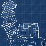
Routed the PCB and added Silkscreen
I added all the components to the PCB, following the tutorial, and wired them together.
This took a lot of time, as I had to mess with clearances, vias, and generally moving things around so they fit on the PCB.


I also added a ground fill, and I spent another hour or two making all the grounds connected to the RP2040.
I added silkscreen of Hack Club, a sword, my gamertag, and a fox and elephant on my friends request.
I'm going to submit this for design review soon, hopefully I can go to prototype :).
Voidless
added to the journal ago
Changed Flash Memory and Began Routing PCB
I had to change the flash memory to have a smaller footprint on the PCB.

I also began routing the PCB.
I had to mess around with the Edge.cuts a lot to make the USB and Battery Connectors fit on the board. I wasn't able to figure out if I did it correctly, so I decided to scrap it and just add neopixels instead later.

Voidless
added to the journal ago
Added Battery Power Implementation and wired I/O Headers
I noticed that the guide mentioned looking at the RPI Pico Datasheet for assistance in adding a battery module, which I wanted to do because it would make the devboard portable.
I read the section of the datasheet about battery power on the RPI Pico, and added the basic implementation with two schottky diodes. I learned that diodes allow one way power. I connected this to one of the pins on the RP2040.
However, it took a while to understand where to implement this, and I learned what GND symbols look like in datasheets and what net labels were.

I think I am done with the schematic now:

It is now time to work on the PCB continuing to follow the tutorial.
Voidless
added to the journal ago
Connected USB, Crystal, and Flash Storage to RP2040
I followed the Custom RP2040 Devboard tutorial until the "Breaking out I/O Pins" section.
I was able to easily follow the tutorial, and understand what each of the pins are for. I also learned that capacitors and resistors are necessary to control the flow of power to ensure that the different components do not get fried.

I also began connecting the header pins to the RP2040 using global labels.
Currently, I am working on adding a battery module so that the RP2040 devboard will work without being connected by USB-C.
Voidless
started Pax the RP2040 Devboard ago
11/23/2025 - Connected USB, Crystal, and Flash Storage to RP2040
I followed the Custom RP2040 Devboard tutorial until the "Breaking out I/O Pins" section.
I was able to easily follow the tutorial, and understand what each of the pins are for. I also learned that capacitors and resistors are necessary to control the flow of power to ensure that the different components do not get fried.
I also began connecting the header pins to the RP2040 using global labels.
Currently, I am working on adding a battery module so that the RP2040 devboard will work without being connected by USB-C.
11/29/2025 8 PM - Added Battery Power Implementation and wired I/O Headers
I noticed that the guide mentioned looking at the RPI Pico Datasheet for assistance in adding a battery module, which I wanted to do because it would make the devboard portable.
I read the section of the datasheet about battery power on the RPI Pico, and added the basic implementation with two schottky diodes. I learned that diodes allow one way power. I connected this to one of the pins on the RP2040.
However, it took a while to understand where to implement this, and I learned what GND symbols look like in datasheets and what net labels were.
I think I am done with the schematic now:
It is now time to work on the PCB continuing to follow the tutorial.
11/29/2025 11 PM - Changed Flash Memory and Began Routing PCB
I had to change the flash memory to have a smaller footprint on the PCB.
I also began routing the PCB.
I had to mess around with the Edge.cuts a lot to make the USB and Battery Connectors fit on the board. I wasn't able to figure out if I did it correctly, so I decided to scrap it and just add neopixels instead later.
12/2/2025 - Routed the PCB and added Silkscreen
I added all the components to the PCB, following the tutorial, and wired them together.
This took a lot of time, as I had to mess with clearances, vias, and generally moving things around so they fit on the PCB.
I also added a ground fill, and I spent another hour or two making all the grounds connected to the RP2040.
I added silkscreen of Hack Club, a sword, my gamertag, and a fox and elephant on my friends request.
I'm going to submit this for design review soon, hopefully I can go to prototype :).