Papa belt
AWD Belted 3d printer, inspired by parts of the babybelt, like the bed being made of iron on patches. but the printers is also optimized for speed and price, this is done through using voron 0 family parts like the bed and x gantry beam
Created by
 William 🚀
16 views
1 follower
William 🚀
added to the journal ago
throwing together the toolhead
i threw together a rough mock of of what sort of position the tool head would be in so i can better anticipate issues i might encounter

as mentioned in the previous journal, ive settled on a variant of the lancer because its geometry seems to work well for an angled belt printer
but there are 3 different lengths


i think the longest one will be the best because
- it has the highest flowrate, which is always nice
- it also is overhangs to the other side of the rail which might help the CG
started throwing together the tool head.
current i would guess the center of the gravity is where the blue cross is, i want it to be where the red cross is.

i want the center of gravity as close to the linear rail, and over the top of it if possible
William 🚀
added to the journal ago
fusion issues and hotend selection
I keep running into issues with fusion not being able to solve my constraints, so im considering deleting all the constraints and making them all again so i dont accidentally over constrain things or create conflicting constraints.
I had originally planned to use a modified dragon Hf, however due to cost and practicality issues ive chosen to use a different hot end
at an angle of 45 degrees the Peopoly lancer long just about clears the heater block

however at 40 degrees the clearance is much comfier so i will use 40 degrees

i was also thinking about how to set the angle of the gantry, i will probably use 3d printed parts so you can more easily remove the gantry or reprint those parts and change the angle of the gantry
i think from the following photo you can tell ive had a "fun" time with constraints

but i did add a double shear rigid motor mount for the two front motors .
William 🚀
added to the journal ago
more gantry+how did it take me 5 years to discover this
its taken me 5 years to realize that you could group sketches and construction things instead of just dealing with a massive list of things


started aligning all the stuff properly
 i dont think i aligned it all well enough though.
currently getting super small angles between things and the X beam which isnt very good at all.
trying to problem solve this.
William 🚀
added to the journal ago
starting the moving part of the gantry
started off by fixing some joints and relationships


realized that i should move the two plates for the x beam closer together, before they were 22mm apart
by moving them 1mm close on each side i make the gap 20mm. which means that it will perfectly hold a 2020 extrusion
still a lot more work to do on this front
William 🚀
added to the journal ago
more gantry work


both of the pulleys for the belts now fit properly in the double shear tensioners
i think the next step is going to be modelling the stuff to support the idlers next

William 🚀
added to the journal ago
almost forgot to replace all the screws
replaced all the m3x40 with m3x45

because my screws were 5mm longer, but i "only" added 4mm in the middle, to avoid the screws going into the motor to deep, or into anything else too far, i extruded all the surfaces on the top plate up by 1mm. which takes it up to 6mm thick.
im slightly worried the 5mm thickness of the bottom plate isn't enough. but only time will tell.
turns out an old sketch wasn't properly constrained.
moving backwards in the timeline was fine, but moving forwards for some reason is incredibly laggy and causes fusion to freeze and me to ultimately need to end the process with task manager.
i fixed the issue of the angle by just remaking it, i repositioned the screws that held it together and made the thread shorter since it really didn't need to be that long given its only moving 5mm.


also had to reconstruct the joints and relationships to get it to all properly move again
this took a lot longer that i expect, but it needed to be done.
William 🚀
added to the journal ago
fixed the motor offset thing
so i work out a way to sort out the motor issue while keeping things printable
First i cut the threaded part off the tensioner

then i moved each of the tensioner halves 2mm away from the central plane

which created a 4mm gap
which i filled in by extending each of the halves by 2mm

however now printing the parts looks tricky
because the whole thread part will overhang
so i slice off that 2mm pieces at the top and bottom

because i already have screws going through everything
it should all just align as part of the stack
ive also just chopped the central part of the housing in half

but i dont like how the printability looks

it looks better split in half
hopefully all of the splitting up doesn't affect the rigidity, the m3x45 bolts should be able to hold it all together tightly and help.
William 🚀
added to the journal ago
placing motors

put the motors tensioners into place.
I also created joints and rigid bodies for the tensioners
there is an issue however.
the motors aren't level

they are 3.9mm out of being level
so thats an issue.
im not quite sure how to fix it since i dont want to use even longer screws
m3x45 feels TOOOO long, and probably expensive.
William 🚀
added to the journal ago
finishing off the tensioners

the more i work through the idea of moving the motors, the more i question if it was a good idea.

Realizing that i need 12, m3x40 bolts per tensioner, so 24 , m3x40 bolts really made me question it given m3 bolts that long are pricey (around $3 for 50).
I say "need 12", however the 8 holding the casing together could be replaced with shorter m3x8 or m3x12 bolts, and bolting the top part to the middle, and the middle to the bottom, however i feel that having a bolt going all the way through, compressing the layers should be better for strength.
thinking about it more, smaller bolts double the number of heat sets, and bolts, so even if the bolts are cheaper the price difference might still be negligible.
Either way, im sticking with the long bolts.
However i want to get this done before dec 31st so I'm sticking with the design that I'm more comfortable with.
I also just prefer to have moving motors.
(the above statement may be copium)

William 🚀
added to the journal ago
did more work on the gantry

ive done a bunch of work on the gantry and now all the blets and idlers are moving and scaling properly when you change the parameters.
i made the gantry parametric so you should be able to scale the printer up or down which was one of the design goals

also starting putting some work into designing the belt tensioner
im aware that moving the idlers is better for input shaper values, however i much prefer moving the motors. for small printers i find that moving the idlers can be difficult due to the space constraints
there was also a chunk of problem solving in trying to get the gantry scaling parametrically.
it turns out the move tool in fusion doesn't like working parametrically, nor does the align tool.
however if you use the "constrain components" tool, and pick align in there, it does work properly with parametric stuff.
:face-palm:
i already had everything as components so nothing changed apart from now i was using the align tool within a different menu.
how fun.
William 🚀
added to the journal ago
more work on belt path

actually properly implemented the belt path, it definitely feels challenging, probably because I've never designed a core XY gantry from scratch before.
but i recon once i get past this stage it should rapidly speed up because I've designed all other parts at least once.
William 🚀
added to the journal ago
Sttarting
i started a BOM so that i can keep track of price

i started by looking at how i wanted to arrange things a bit.

then it came to the thing im most scared of, the belt path.
At first it seemed super magical and intimidating
so i decided to draw out the beltpath for the monolith gantry and see how that worked

which helped me realise some of the relationships and dimensions etc

so then i could draw out this and use this to start doing something in CAD
ive tried to keep everything parametric so that i could make the printer bigger if i wanted, perhaps 180mm^2 instead of the current plan of 120mm^2

it does look like a bit of a mess but hopefully it can still come together nicely
William 🚀
started Papa belt ago
12/15/2025 - Sttarting
i started a BOM so that i can keep track of price
i started by looking at how i wanted to arrange things a bit.
then it came to the thing im most scared of, the belt path.
At first it seemed super magical and intimidating
so i decided to draw out the beltpath for the monolith gantry and see how that worked
which helped me realise some of the relationships and dimensions etc
so then i could draw out this and use this to start doing something in CAD
ive tried to keep everything parametric so that i could make the printer bigger if i wanted, perhaps 180mm^2 instead of the current plan of 120mm^2
it does look like a bit of a mess but hopefully it can still come together nicely
12/20/2025 - more work on belt path
actually properly implemented the belt path, it definitely feels challenging, probably because I've never designed a core XY gantry from scratch before.
but i recon once i get past this stage it should rapidly speed up because I've designed all other parts at least once.
12/27/2025 - did more work on the gantry
ive done a bunch of work on the gantry and now all the blets and idlers are moving and scaling properly when you change the parameters.
i made the gantry parametric so you should be able to scale the printer up or down which was one of the design goals
also starting putting some work into designing the belt tensioner
im aware that moving the idlers is better for input shaper values, however i much prefer moving the motors. for small printers i find that moving the idlers can be difficult due to the space constraints
there was also a chunk of problem solving in trying to get the gantry scaling parametrically.
it turns out the move tool in fusion doesn't like working parametrically, nor does the align tool.
however if you use the "constrain components" tool, and pick align in there, it does work properly with parametric stuff.
:face-palm:
i already had everything as components so nothing changed apart from now i was using the align tool within a different menu.
how fun.
12/28/2025 3 AM - finishing off the tensioners
the more i work through the idea of moving the motors, the more i question if it was a good idea.
Realizing that i need 12, m3x40 bolts per tensioner, so 24 , m3x40 bolts really made me question it given m3 bolts that long are pricey (around $3 for 50).
I say "need 12", however the 8 holding the casing together could be replaced with shorter m3x8 or m3x12 bolts, and bolting the top part to the middle, and the middle to the bottom, however i feel that having a bolt going all the way through, compressing the layers should be better for strength.
thinking about it more, smaller bolts double the number of heat sets, and bolts, so even if the bolts are cheaper the price difference might still be negligible.
Either way, im sticking with the long bolts.
However i want to get this done before dec 31st so I'm sticking with the design that I'm more comfortable with.
I also just prefer to have moving motors.
(the above statement may be copium)
12/28/2025 5 AM - placing motors
put the motors tensioners into place.
I also created joints and rigid bodies for the tensioners
there is an issue however.
the motors aren't level
they are 3.9mm out of being level
so thats an issue.
im not quite sure how to fix it since i dont want to use even longer screws
m3x45 feels TOOOO long, and probably expensive.
12/28/2025 3 PM - fixed the motor offset thing
so i work out a way to sort out the motor issue while keeping things printable
First i cut the threaded part off the tensioner
then i moved each of the tensioner halves 2mm away from the central plane
which created a 4mm gap
which i filled in by extending each of the halves by 2mm
however now printing the parts looks tricky
because the whole thread part will overhang
so i slice off that 2mm pieces at the top and bottom
because i already have screws going through everything
it should all just align as part of the stack
ive also just chopped the central part of the housing in half
but i dont like how the printability looks
it looks better split in half
hopefully all of the splitting up doesn't affect the rigidity, the m3x45 bolts should be able to hold it all together tightly and help.
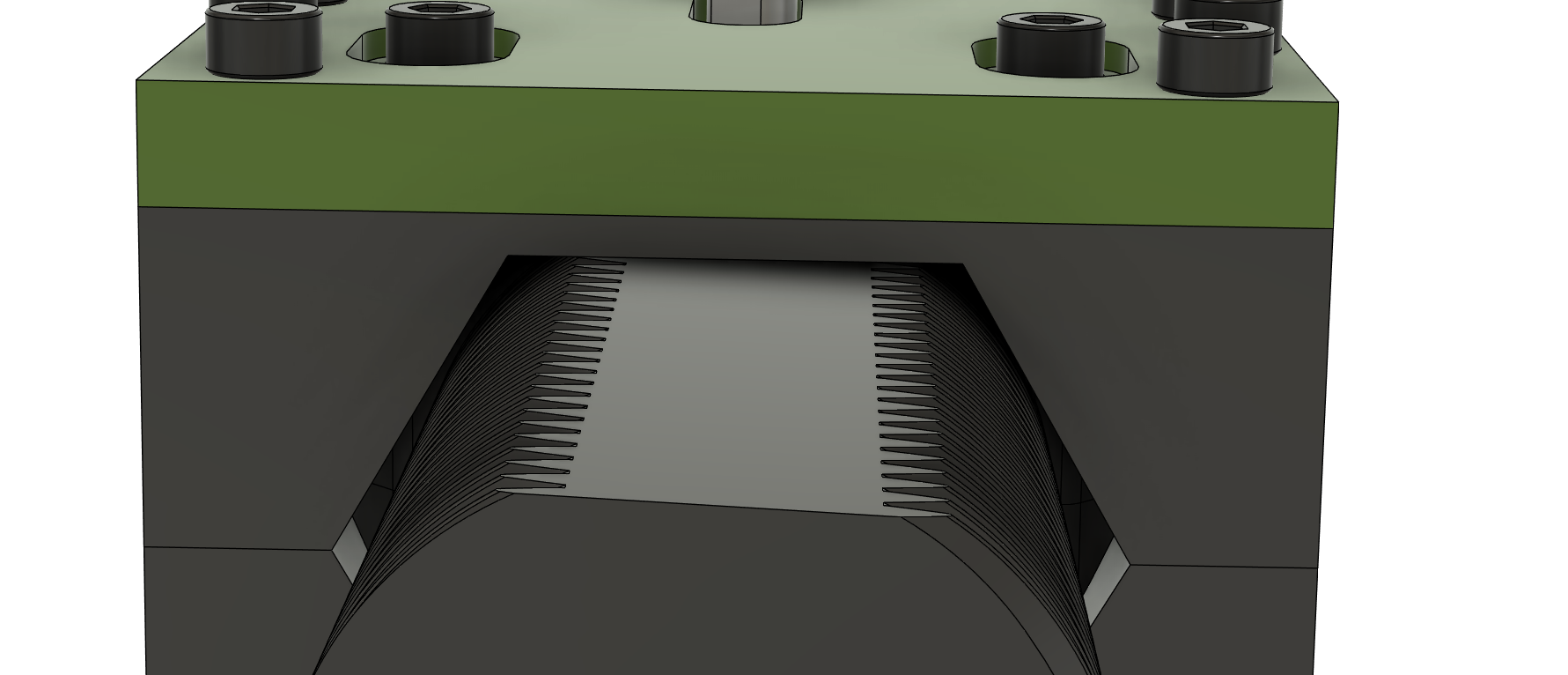
12/28/2025 5 PM - almost forgot to replace all the screws
replaced all the m3x40 with m3x45
because my screws were 5mm longer, but i "only" added 4mm in the middle, to avoid the screws going into the motor to deep, or into anything else too far, i extruded all the surfaces on the top plate up by 1mm. which takes it up to 6mm thick.
im slightly worried the 5mm thickness of the bottom plate isn't enough. but only time will tell.
![image](/user-attachments/blobs/proxy/eyJfcmFpbHMiOnsiZGF0YSI6MzE0MjMsInB1ciI6ImJsb2JfaWQifX0=--8a1abb6651b1cd631e67f7c9257284f70a38df18/image.png
also spent a bit of time trying to fix a weird angle that appeared
turns out an old sketch wasn't properly constrained.
moving backwards in the timeline was fine, but moving forwards for some reason is incredibly laggy and causes fusion to freeze and me to ultimately need to end the process with task manager.
i fixed the issue of the angle by just remaking it, i repositioned the screws that held it together and made the thread shorter since it really didn't need to be that long given its only moving 5mm.
also had to reconstruct the joints and relationships to get it to all properly move again
this took a lot longer that i expect, but it needed to be done.
12/28/2025 10 PM - more gantry work
both of the pulleys for the belts now fit properly in the double shear tensioners
i think the next step is going to be modelling the stuff to support the idlers next
12/29/2025 - starting the moving part of the gantry
started off by fixing some joints and relationships
realized that i should move the two plates for the x beam closer together, before they were 22mm apart
by moving them 1mm close on each side i make the gap 20mm. which means that it will perfectly hold a 2020 extrusion
still a lot more work to do on this front
12/31/2025 - more gantry+how did it take me 5 years to discover this
its taken me 5 years to realize that you could group sketches and construction things instead of just dealing with a massive list of things
started aligning all the stuff properly
i dont think i aligned it all well enough though.
currently getting super small angles between things and the X beam which isnt very good at all.
trying to problem solve this.
1/5/2026 - fusion issues and hotend selection
I keep running into issues with fusion not being able to solve my constraints, so im considering deleting all the constraints and making them all again so i dont accidentally over constrain things or create conflicting constraints.
I had originally planned to use a modified dragon Hf, however due to cost and practicality issues ive chosen to use a different hot end
at an angle of 45 degrees the Peopoly lancer long just about clears the heater block
however at 40 degrees the clearance is much comfier so i will use 40 degrees
i was also thinking about how to set the angle of the gantry, i will probably use 3d printed parts so you can more easily remove the gantry or reprint those parts and change the angle of the gantry
i think from the following photo you can tell ive had a "fun" time with constraints
but i did add a double shear rigid motor mount for the two front motors .
1/7/2026 - throwing together the toolhead
i threw together a rough mock of of what sort of position the tool head would be in so i can better anticipate issues i might encounter
as mentioned in the previous journal, ive settled on a variant of the lancer because its geometry seems to work well for an angled belt printer
but there are 3 different lengths
i think the longest one will be the best because
- it has the highest flowrate, which is always nice
- it also is overhangs to the other side of the rail which might help the CG
started throwing together the tool head.
current i would guess the center of the gravity is where the blue cross is, i want it to be where the red cross is.
i want the center of gravity as close to the linear rail, and over the top of it if possible