X-26 GREYWOLF PT-1
This beast, A single engine powered, housing an 80mm EDF in its engine bay. 1.3 meters long, standing .3 meters high. Is the first Prototype of one of my wonderworks of single engine powered series of a highly agile Rc fighter jet, currently in prototyping state, its intended to house a Custom diy Radar that can track and lock on objects it considers hostile. And a telemetry system which can help locate aircraft's altitude, distance from the controller, its heading, and location for google maps, in mid-flight. ---------------------------------------------------------------------------------- Note this project only covers the building of the frame, other components like landing gears, control surfaces, and the electronics needed for basic functionality.
Created by
 M.Abdullah
Tier 2
564 views
13 followers
 cubit010 ⚡
requested changes for X-26 GREYWOLF PT-1 ago
cubit010 ⚡
requested changes for X-26 GREYWOLF PT-1 ago
you submitted to stasis, please stop submitting it here
M.Abdullah
submitted X-26 GREYWOLF PT-1 for ship review ago
M.Abdullah
added to the journal ago
Shifting to STASIS
yes ive shifted to stasis IDk why but i did it, and i think i did the right thing
As I'll have more time to actually build it, rather then just it being sitting around useless
 Shadow
requested changes for X-26 GREYWOLF PT-1 ago
Shadow
requested changes for X-26 GREYWOLF PT-1 ago
user submitted to stasis-
M.Abdullah
submitted X-26 GREYWOLF PT-1 for ship review ago
M.Abdullah
added to the journal ago
Making the rotating mechanism for the STABS!
So as the mechanism for the stabs rotating was also required. SO, i made tht too.
For that I copied the servo and moved it to the place where the stabs rod could be set easily without disturbing the efficiency of the rotation.
I placed it almost parallel to the direction of rear edge of the stab.
then moved to positioning the servo.
I tried to position the servo just in front of the stabs rod, but the servo was coming out of the fuselage skin and adding the concern of more drag.
So, I positioned it in such a place that it won't affect the centre of gravity of the plane much .
ANd balancing would be same, SO I placed almost a centimetre or half away from the actual rod, then made a small hook type for making the rod rotatable from a bit far position.
then made a rod for rotating the rod. and umm.
Ah yess.
Then made the supports for holding the servo ,and made another support perpendicular to the first one To hold the rod ,and fit in a ball bearing for allowing for a smooth rotation.
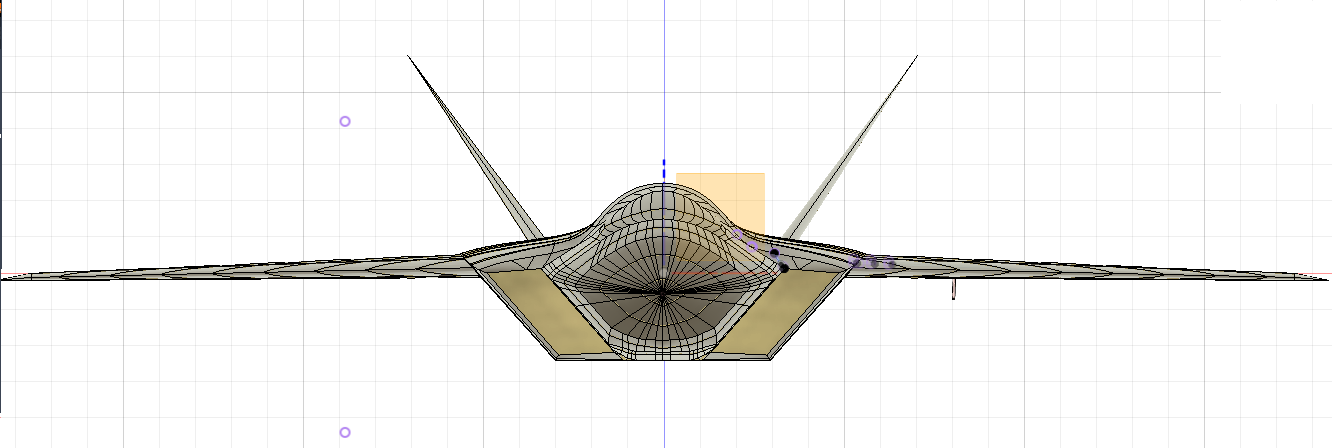
Also U'll see an edf there, I forgot to tell ya that ,
I imported a model of the edf to see whether ,I had made the engine bay accurately.
And Surprisingly with tolerences included I HAD MADE A PERFECTLY ACCURATE ENGINE BAY!!!!!!!!!
OH MY YESSHHHHHHHHHHHHHHHHHHHHH!
.png)
.png)
M.Abdullah
added to the journal ago
DONE!!?
Am i done ,
actually no!!.
Still many things left to tell ya
So now I'm talking about the flaps and the ailerons!
So here they are
.png)
.png)
.png)
Eh!, ive had enough and this would be the last journal, or not.
So, first of all I made the flaps and aileron's outlines in ma mind, then copied them to the fusion
and kept the non-touching outlines kinda extended cuz, i wanted a clear cut flap, So after that I extruded the edges only, to slice through the wing screen and any of the ribs in between, Then I sliced the wing skin and the ribs, Then i Did same for the aileron, and punched ailerons and flap for one wing, then did same for the other wing . ANd punched flaps and ailerons in both wings.
After that I imported the model of an Sg-90 180 degrees rotation Servo and placed it right in front of the middle of the flap, then made a curved cover for the servo, and a plane where the servo is going to be mounted , then I did same for the ailerons , and made the cover for its servo too.
M.Abdullah
added to the journal ago
Concerned abt the wing structure
As i was concerned I asked the GPT to analyze the structure and u know what he said?
He said that my wing Structure was good, but not very good and had those
irregualr triangluations which werent efficient for ma goal speed.\
IM cooooooooooooooooooooooooooooked

Eh!,I think I'll have to redesign the wing!!
but eh!, i aint doin tht , idont have enough time left to do , so im good with simple wings
M.Abdullah
added to the journal ago
Ah i forgot another thing
I forgot to tell ya guys tht I also Had made the spars and ribs for the wings.
And that was way before, before then i made the stabs!!
Eh! Btw here's the process.
The Process:-
the process was same as before.
Make patches, place them where they were rewuired the most for the spars, like leading spar, after the place for the slat,
The middle spar at the middle for max support, and some what parallel to the leading spar.
Then I made the first patch for the ribs!.
Made it parallel to the leading spar. and made rectangular pattern for the ribs to about 7 ribs.
then sliced the end of the ribs with the middle spar, for makin a triangular shape for better stiffness, and making the wings to be strong enough to hold the pressure of the air at high speeds.
Then sliced the ribs using the wing's surface. then removed the extra surfaces.
and then made the mirror of the leading ribs at their end hence making a strong structure for the wing,ACCORDING TO ME, but may require changes here take a look:
.png)
.png)
M.Abdullah
added to the journal ago
Adding the Airduct
As the airduct is the most essential part of the aircraft. So, I had to design it in such a way that the air wont get turbulent inside the duct and damage the Edf, And for tht I kept the front a bit straight then added a diagonal gradually increasing slope tht goes up in two dimensions, then made a downward slope and tried keeping it gradual too and made it to the engine bay's front.
And I had to sketch all of it myself no clues at all, only my thought and me.
And had to set the curvature of the lines several times for not making an idiot mistake.
Cuz tht could result in a dangerous accident and may burn down, or tore away the duct itself, or reslut in major error in ma beloved EDF, which I want so badly tht im re-typing all of the journals another time.
So I tried two different types of design Both of them are as follows:-
.png)
.png)
Now both have completely different middle parts, one has gradual one directional slope while the other has two directional slopes and a bit more curvature.
And I choosed------- the----- first one!!, cuz of many factors,
Like I looked of the amount of hinderence each was causing in direct line of sight for the engine face, and a divereted look for seeing how much engine's face, each duct was hiding and both Had same ratios.
Secondly the first one was likely to cause much less or no turbulence at high speeds,
While the second one had likely higher chances of duing that and which was dangerous to try so, I simply chose the First Duct.
here are some more of the views.
First Duct design:-
Second Duct design:-
And seriously that took me two days design both of them and finally choosing the first design.
.png)
.png)
.png)
.png)
.png)
.png)
M.Abdullah
added to the journal ago
Adding new tails to the plen.
So after getting that ugly looking tail, I decided to make a new one , thts much better than the one before.
So I took F-35 as a reference and started sketching outlines for the new tail.
I made the outline to be swept back at an angle greater than 50 degrees, and I made them to be small for lowering the drag ratio,
also bent the tail to make it look stealthy, hehe.
So, after sketchign the outline, then I bent the sketch a bit, and then made the aerofoil at the lower root , then made some helping rails , and then lofted the tail , and then u can see in the ss that im positioning it..png)
After getting a perfect position for the stab, I mirrored it on the other side and got a perfect shape for my wolf, Btw it looks awesome with out the canopy, Doesn't it.
.png
.png)
.png)
And the only thing remaining is the air duct, tht is supposed to be an S-duct.
M.Abdullah
added to the journal ago
Making the ugly tail
Finally I moved to making the tail which I already had half sketched a long time ago. So I simply finished sketching the tail, and its base and made some improvements in the previous sketch to make it look more better and more good for ma design, at start it looked fine but after lofting the plae looked like this ☠
.png)
.png)
.png)
And I started asking myself wht the hell Shi* I have made.
Like look at this Sh** its worsening ma WOLF's Image mann,
And I literally started hating that design, which was looking fabulous
In blender design, I guess changing the environment changes the perspective of a man
And the same happened with me. AHH!!
And I started laughing at myself, Btw I had it removed imidiately.
M.Abdullah
added to the journal ago
Adding stabs!!
### NOW ABOUT THE STABS
so basically a stab, properly "stabilator", Is a horizontal tail tht can move freely as a whole without any other moveable parts required for getting control over pitch and dive. U can say that its a stabilizer just rotating in one piece.
Ah I forgot to tell another thing, That I also tilted the wing a bit downward, for just increasing the instability of the plane, which in turn increases the manoeuvrability, hehe.
now back,
So first of all I sketched the outlines of the stab, made it like a blend of F-22's and F-16's stabs,
Then made the aerofoil at the root of the stab, and checked if it overlapped with the edge of trailing edge of the fuselage or not, and sadly it didn't overlap. And for better and smooth airflow the overlap was necessary!!. So for that I first tried changing the shape of the aerofoil but that didn't help, and I had to change the upper curvature of the trailing edge itself to solve the issue, and in meantime I also looked at the F-22's blueprint and found the same thing. So I edited the rear sections again and this time made only a slightly difference from the previous one, and as a result I got a smooth and gradual depression (thts an angle name).
And finally got the overlapping i was finding , and finally lofted the stab, .png)
.png)
Also I did make the engine nozzle too, tht i forgot to mention above.
I For tht I took the measurement of the EDF's outer diamter in ma mind, and made sure tht the start of the engine nozzle is from between
80 and 85mm diameter
ANd before making the nozzle I had to Mke the engine cover first , the part between the fuselage and the nozzle, as I call it so. So, I simply made a sketch, drew a line from the very end of the fuselage to the place where I thought was good, made a circle of dia between 85 and 80 mms. aNd made some rails for helping in the lofting of the part, then I made another circle enough far from the end of engine cover where I felt was good , and after that final circle, I finally lofted the remaining parts of the fuselage.
M.Abdullah
added to the journal ago
Giving new Wings to the beast
As the design of the older wings wasn't fitting the theme of this beast and it made it look funnier than making it more aggressive,
So now i wanted a design that gives ma beast an aggressive look,
And believe makin a new wing design from scratch aint that easy than it looks, but AS I'm Me, so i don't know how but i did it, and made a new wing design that gives ma lovely beast aggressive look and makes it similar to the American F-22 and F-35.
So the total wingspan of the aircraft is likely 93-95 cm's and trust me that aint a bad wingspan for this body as to me, but the wings are only a bit smaller than the f-22 if compared at the same scale.
Also, the wings are placed a bit behind from the F-22's.But Eh! what can i do I'm making my own design and that's not an easy thing to do.
Now back to the topic.
So, the wings are a bit smaller than of F22, and have slightly less swept back angle than the f22's. As the aircraft is in Prototyping stage so, many mistakes can occur and thts why im already thinking of the changes to bring in the Pt-2 of Single engine series. i.e. the PT-2SE, cuz there's already Pt-2 going on in ma brain, so there will be two Pt-2s.
The PT-2SE and PT-2TE
Now back,
After successfully sketching the aerofoils at root and tip of the wing and for this I first relied on the Ai-made supersonic capable aerofoils, but they were quite too thin and required some changes so i Just made a new hand-made aerofoil similar enough to the Ai-made.
then made the helping rails, and lofted the wings surface. OOOOOOOOOOOOOOOOOOOh yeah
After that I moved to fixing the curving of the trailing edge.
For tht I had to change the depth of the rear sections of the plen. And i did change the curving type,
from a steep curve its now a gradual curve
Here's how It looks.png)
ANd the WINGG
.png)
.png)
M.Abdullah
added to the journal ago
Further Advancements
While looking at the ss of first canopy loft.
I thought I had to improve the design of the canopy and fix the last section of the nose section.
So, I first keeping in mind the future integrations into the plane, especially the canopy, I changed the length of the canopy also changed the height of the canopy, and changed the curving of the canopy, also lofted the last section of the nose section by using the side outline of the canopy, and fixed the last section of the plane, and mirrored the canopy on the other side and merged the whole canopy, Also I opened the doors of the landing gear's bay.
And i figured out that I had made the doors opposite to the direction i was wanting to, so I just decided to change the direction as it was looking not umm good.
Also, I re-lofted the lost deflector part of the inlet, and I discovered some error in the deflector, that it was intersecting with the nose section, So I also fixed that error too and some gap between the deflector and the nose section, before they met at the same edge.
.png)
Also forgot to mention tht I also did complete sketching the trailing edge of the fuselage, and also did complete lofting it, But i discovered an error in it tht I had made it like suddenly make steep curving which is very bad to smooth air flow and can result in high chance of turbulence, So I decided to look at the F-22's blueprint and fix the curving with my own vision, But unfortunately I also forgot to do that for now.
M.Abdullah
added to the journal ago
Making the Canopy
Eh!
I forgot I was talking about, So yes, I remember now what I was talking about.
So yes, I lofted the canopy, using the sketches, after that I mirrored it, the canopy on the other side
and then discovered a fault in the last part of the nose section, So i just removed that part Simply,
And forgot fixing it 😁.
So, I moved up on and made the Landing gear segment. First, I completed sketching the segment for making the segment. For that I consulted the blueprint of the F-22 and further its lower view,
then made the lower segment of the landing gears, and also the doors of the landing gear bay. And I thought I don't have the SS having the landing gear's bay open .
Also While this process I lost the deflector sadly 😪
.png)
.png)
ALso heres another enlarged ss of the situation , as u can see the trailing edge of the fuselage is still missing and pending for being lofted and also u can see my dumb design of the tail which I Forgot to look over. in next few logs..png)
.png)
 PriXy
gave kudos to X-26 GREYWOLF PT-1 ago
PriXy
gave kudos to X-26 GREYWOLF PT-1 ago
Idk what you yapping here but cool
M.Abdullah
added to the journal ago
Marching Forward
After successfully lofting the nose section of the plane, It was time to head forward,
So, i further sketched the rails and the outlines, of the remaining part of the fuselage.
then fixed the curvature of the rails fixed their curving angles. And then using the surface loft tool i Lofted the remaining sections of the fuselage on by one.
Then moved to sketching the first sketch of a canopy, first sketched the outline from my own imagination , then made the horizontal outline of the canopy, then skecthed the vertical sections at various points , and fixed the curbing angles, bu for now only sketched the canopy and the sections for it but not lofted it, Here take a look at the result
--------------------------------------------------------------------------------------------------------.png)
Also, you'll see a landing gear there, that's a model I've imported from the Grab CAD for making a section in the nose section for fitting in the front landing gear of the plane.
Also, I forgot to mention that I also sketched the upper, lower, side, and inner outlines of the inlets, then made the helping the rails, fixed the curvature of the rails, lofted it, and got a somewhat not liked inlet, then looked at the inlets of the F-22 and discovered somewhat curving in the inlets, So i just decided to make the curving in the inlets of my plane too, and then adjusted the curvature of the rails again, then inserted curvature in the lower outlines of the plane.
Then again readjusted the rails and re-lofted the inlets. Then sketched the deflector segment of thhe inlets, and made some rails for lofting that segment, then lofted the deflector segment of the inlets
successfully. And then lofted the base segment of the plane.
And then started sketching the segments for making the section for the front landing gear.
M.Abdullah
added to the journal ago
New Milestone
While comparing the wing the body i felt like ive made it look funny, so i just hid the wing from my view
so tht i can work on other parts.
After learning the new surface lofting without using the form tool, I decided to amend the already existing nose section, and make it in surfaces, so I just simply removed the old lofts, and while readjusting everything I also changed my mind about the engine going to be used, First I thought of using a 70mm EDF but lookin at the size of the plane I decided to step onto 80mm EDF due to the power|thrust|and speed capabilities it was going to add to the plane, Also a plane with an 80mm EDF will be much more easily visible than a small plane of almost a hundred centimetres, Also adding much more experimenting capability, So For tht I searched up the web and found out the outer diameter of the EDF, likey about 85mm.
here are the dimensions from the manufacturing company
.png)
.png)
So, I had to change the skecthes of the sections, and scale em up, so i did the same, grabed the sections' sketches and scaled em up untill i got a perfect circle in the last section with having support tolerences of few centimeters up and down the circle,for support.
Then I resketched the upper and lower outlines of the plane fixed the curvature, and then made the side outline and then fixed its curvature too,
Then made a quiet number of helping rails fixed the curvings and curvatures, and then finally lofted the first successful nose section of the final idea. Here's how it looks(as i dont have ss from the work i did along with journaling. So, i had to take the ss of the part from current final model)
.png)
.png)
.png)
M.Abdullah
added to the journal ago
Makin the Ribs and spars of the wing
After making the wing As i was following a tutorial, as i was a complete beginner in this field, So as wht the man did i did the same.
So i while following the tutorial and getting hints just closed the tutorial and set sail to
make ma own journey. And made first spars, as i learnt, made a patch and set the curving angle and place of the patch, made secondary patch and placed it where i felt was right, and then made the trailing spars patch, splited the patches along the surface of the wing , and got fancy spars. Then i headed to making the leading ribs
for tht i made a new patch , placed it to the right angle of leading spar and made rectangular patterns like for 10 frames ,then splited em along the leading spar, removed the extra surafces, and then splited the patches using the wings surafcs and got the spars and ribs for the wings!!,.png)
M.Abdullah
added to the journal ago
Going OFF to First wing design and the mid fuselage
Eh!!.I Forgot to mention, the lofted parts of the nose were solid!, not surfaces dat I lofted after getting to middle of the modelling.
So, After lofting the front part of the fuselage I mean the nose section, I moved to making the mid part of the fuselage which wasn't much refined but umm I just lofted just solid lofted it and moved to making the wing.
Outlined the wing according to the one i made in blender. made aerofoils at root and tip, made helping rails, and made a form, and lofted the wing, discovered some errors like "Failed to solve the spline" fixed that error by merging all of the edges and finished the form, But discovered tht it aint workin for me so I , just simply surface lofted the wing, without makin the form, Unfortunately I have only one Ss for this milestone and the next milestone.Here's the ss
.png)
M.Abdullah
added to the journal ago
Hitting the Next road
After refining the Model, and the sections in the blender, I imported the model into the fusion and started just looking at the model.
Seriously, i was just sitting dumb,
Then i figured out to edit the model and just leave the sections
I'm not going to talk about the dumb mistakes I made in the starting
So, I learnt the new technique of Surface lofting, for that I first of all sketched all of the sections, by removing the sections one by one, and placed the sketched sections in the places where I had put them in the blender model. After Sketching the Forward nose sections, and sketching new rails and fixing their curvatures I lofted the nose section. Here's how it looked, also some of the sses during the Process.
.png)
.png)
.png)
.png)
.png)
.png)
Those components u're seeing in the screenshots.
Are my dumb mistakes. As I only first thought of extruding sketches, which I successfully fixed through the tutorial
And tried to remove them but it wold only result in downstream failuire so I just left them.
M.Abdullah
added to the journal ago
Refining the design
After making the blueprints, i got into blender learnt some basic modelling, and started off to making the model of the idea plane, for tht I got the blueprints scanned to pdf, imported them in blender and started working, as I learnt, I used the plain mesh as primary for modelling. AS I just starting making the sections, I came to know that the original blueprints had some errors, For fixing which I , instead of going back to pages. decided to Fixed em all inside the Blender, and got some new better then before, sections then placed those sections at the right places, Aand started surfacing using new meshes.
Completed surfacing the fuselage. then moved to the wings. For wings i imported the blueprint 
which is ofc of f16's wings, so i tuned the mesh according to these aerofoils, and made a wing almost like the wing of f16 . After that i moved to making the stabs, following same techniques, as I first decided to make it single tailed, so similarly Following same procedure I made the tail too.
And in this way i completed modelling the plane. Eh!! but the side of nose was left due to my discovery of Fusion and getting tired of Blender. Btw this is how the plane looked In Blender.png)
.png)
.png)
.png)
U can say that this model was the foundation of the model I was able to make in Fusion.
PriXy
gave kudos to X-26 GREYWOLF PT-1 ago
you need get aproved!!!
M.Abdullah
added to the journal ago
Starting OFF
So, here comes the timeline progression of the project
The Start
As every project, like mine, needs blueprints for starting. So, first of all I worked on the blueprints
as this plane is a custom| my own design so, I got the blueprints , with cutaway sections. Then sketcehd the whole blueprint on my own page, edited the side shape of the plane, made it like the f22.
Got the sections, edited them and made em like the f22's just to make it look stealthly,
HERE is the view of the first blueprint.

(sorry thats a bit messy cuz i was discussing things with an ai)
Then moved to the upper view part of the blueprint/
As I made the sections' designations in the first blueprint According to f-16s blueprint, so, i measured the distance between every section, made those markings on the second blueprint. And started joining corners of the sections, And in this way i got a rough shape for the plane, which ofc i refined later, made the lines curved, made some changes in the first blueprint, and got the outer shape of the plane. After completing the fuselage, i moved to making the wings, in the blueprints that i had drawn, there are actually two wings and two types of stabs, tht was due to my lack of knowledge at tht time, also i discovered things and refined the design, btw here is the second blueprint

 divyamary115
gave kudos to X-26 GREYWOLF PT-1 ago
divyamary115
gave kudos to X-26 GREYWOLF PT-1 ago
so much determination to fix every mistake which was crazy cause you get rejected so many times 👏
PriXy
gave kudos to X-26 GREYWOLF PT-1 ago
:( i agree that
 CAN ⚡🚀
requested changes for X-26 GREYWOLF PT-1 ago
CAN ⚡🚀
requested changes for X-26 GREYWOLF PT-1 ago
Your journal needs to show the step-by-step process you took in making this project. Please break your larger journal entires into multiple smaller ones, show the steps you took, and explain it better.
 raynoldbenhin7.1
gave kudos to X-26 GREYWOLF PT-1 ago
raynoldbenhin7.1
gave kudos to X-26 GREYWOLF PT-1 ago
wow men what great project,i wish i could get the resources like how you did bro ,keep on going
 Sunrit
gave kudos to X-26 GREYWOLF PT-1 ago
Sunrit
gave kudos to X-26 GREYWOLF PT-1 ago
Great project! You have been waiting a long time...
M.Abdullah
submitted X-26 GREYWOLF PT-1 for ship review ago
 samliu ⚡🚀
requested changes for X-26 GREYWOLF PT-1 ago
samliu ⚡🚀
requested changes for X-26 GREYWOLF PT-1 ago
Hi, I see on your GitHub repo it says: "Total Time Spent: 3+ years". Unfortunately, we cannot accept projects that were mostly made before Blueprint started on October 1st, 2025.
M.Abdullah
submitted X-26 GREYWOLF PT-1 for ship review ago
 PenguinMo
requested changes for X-26 GREYWOLF PT-1 ago
PenguinMo
requested changes for X-26 GREYWOLF PT-1 ago
hi, this looks really cool, your CAD is looking clean, but you need to add your source files for your CAD editor, example for Fusion you need .f3d to make sure you are not faking anything make sure u take a look at https://blueprint.hackclub.com/about/submission-guidelines before submitting, besides this everything is looking really polished up, can't wait to see you build this!
PriXy
gave kudos to X-26 GREYWOLF PT-1 ago
i like that
M.Abdullah
submitted X-26 GREYWOLF PT-1 for ship review ago
 zsharpminor ⚡
requested changes for X-26 GREYWOLF PT-1 ago
zsharpminor ⚡
requested changes for X-26 GREYWOLF PT-1 ago
Hi, as the previous reviewer has said, this can only qualify as a Tier 2. Additionally, please try to find cheaper alternatives for your BOM items - $110 for shipping is mildly insane. Thanks!
 simonfrellesen
gave kudos to X-26 GREYWOLF PT-1 ago
simonfrellesen
gave kudos to X-26 GREYWOLF PT-1 ago
This is sick, i really want to hear more to it. If you've got time and wanna tell me abit more about the project could you add me on discord? Username is frellefar
M.Abdullah
submitted X-26 GREYWOLF PT-1 for ship review ago
 Johan
gave kudos to X-26 GREYWOLF PT-1 ago
Johan
gave kudos to X-26 GREYWOLF PT-1 ago
Nice, Good Luck
 Iamalive 🚀
requested changes for X-26 GREYWOLF PT-1 ago
Iamalive 🚀
requested changes for X-26 GREYWOLF PT-1 ago
Your project does not qualify as a tier 1, at most a tier 2. Also, please add all the screenshots of the parts you're buying in your cart. Additionally, your current cart total is 96057 PKR, which is only $342.87 USD.
 Gethin
gave kudos to X-26 GREYWOLF PT-1 ago
Gethin
gave kudos to X-26 GREYWOLF PT-1 ago
Love it hope the build goes well
M.Abdullah
submitted X-26 GREYWOLF PT-1 for ship review ago
PenguinMo
requested changes for X-26 GREYWOLF PT-1 ago
This looks really nice but is there anyway you can cub the radio transmitter for something else maybe you could build you're own or find and alternative part, this is all you need to make this project a real thing
M.Abdullah
submitted X-26 GREYWOLF PT-1 for ship review ago
Iamalive 🚀
requested changes for X-26 GREYWOLF PT-1 ago
Your BOM should have links to the actual item you're buying from. Also, we don't allow buying expensive premade parts such as that radio transmitter.
M.Abdullah
submitted X-26 GREYWOLF PT-1 for ship review ago
PenguinMo
requested changes for X-26 GREYWOLF PT-1 ago
There are somthings you need to fix 1 your price of your parts is over 400 and all CAD files need to be in.step
M.Abdullah
submitted X-26 GREYWOLF PT-1 for ship review ago
 1mon ⚡
requested changes for X-26 GREYWOLF PT-1 ago
1mon ⚡
requested changes for X-26 GREYWOLF PT-1 ago
please update your journal so the hour counts are accurate! also please upload cart screenshots that show what your buying for this project! also, links in your repo are 404ing.
 Hashim 🚀
gave kudos to X-26 GREYWOLF PT-1 ago
Hashim 🚀
gave kudos to X-26 GREYWOLF PT-1 ago
Looks like a f35 with that front and rear wing profile. Really cool project. Hope you finish it! But I don’t see if you worked its electronic and engine out?
M.Abdullah
submitted X-26 GREYWOLF PT-1 for ship review ago
 cyberbrainiac
gave kudos to X-26 GREYWOLF PT-1 ago
cyberbrainiac
gave kudos to X-26 GREYWOLF PT-1 ago
yo this is awsome
 kwanyeung.chow1 🚀
gave kudos to X-26 GREYWOLF PT-1 ago
kwanyeung.chow1 🚀
gave kudos to X-26 GREYWOLF PT-1 ago
nice model, very fancy
 shajamin2010
gave kudos to X-26 GREYWOLF PT-1 ago
shajamin2010
gave kudos to X-26 GREYWOLF PT-1 ago
hobby purpose?! someone hire this guy pleassseeee this is sooo cool
 kentonscribner
gave kudos to X-26 GREYWOLF PT-1 ago
kentonscribner
gave kudos to X-26 GREYWOLF PT-1 ago
Incredible project! Im glad you have the dedication to do this! Also, if your interested check out my design! (https://blueprint.hackclub.com/projects/1302)
 -JustACoder (Don't cuss around me pls) 🚀
gave kudos to X-26 GREYWOLF PT-1 ago
-JustACoder (Don't cuss around me pls) 🚀
gave kudos to X-26 GREYWOLF PT-1 ago
Looks cool!!
M.Abdullah
started X-26 GREYWOLF PT-1 ago
3/27/2026 3 AM - Starting OFF
So, here comes the timeline progression of the project
The Start
As every project, like mine, needs blueprints for starting. So, first of all I worked on the blueprints
as this plane is a custom| my own design so, I got the blueprints , with cutaway sections. Then sketcehd the whole blueprint on my own page, edited the side shape of the plane, made it like the f22.
Got the sections, edited them and made em like the f22's just to make it look stealthly,
HERE is the view of the first blueprint.
(sorry thats a bit messy cuz i was discussing things with an ai)
Then moved to the upper view part of the blueprint/
As I made the sections' designations in the first blueprint According to f-16s blueprint, so, i measured the distance between every section, made those markings on the second blueprint. And started joining corners of the sections, And in this way i got a rough shape for the plane, which ofc i refined later, made the lines curved, made some changes in the first blueprint, and got the outer shape of the plane. After completing the fuselage, i moved to making the wings, in the blueprints that i had drawn, there are actually two wings and two types of stabs, tht was due to my lack of knowledge at tht time, also i discovered things and refined the design, btw here is the second blueprint
3/27/2026 4 AM - Refining the design
After making the blueprints, i got into blender learnt some basic modelling, and started off to making the model of the idea plane, for tht I got the blueprints scanned to pdf, imported them in blender and started working, as I learnt, I used the plain mesh as primary for modelling. AS I just starting making the sections, I came to know that the original blueprints had some errors, For fixing which I , instead of going back to pages. decided to Fixed em all inside the Blender, and got some new better then before, sections then placed those sections at the right places, Aand started surfacing using new meshes.
Completed surfacing the fuselage. then moved to the wings. For wings i imported the blueprint
which is ofc of f16's wings, so i tuned the mesh according to these aerofoils, and made a wing almost like the wing of f16 . After that i moved to making the stabs, following same techniques, as I first decided to make it single tailed, so similarly Following same procedure I made the tail too.
And in this way i completed modelling the plane. Eh!! but the side of nose was left due to my discovery of Fusion and getting tired of Blender. Btw this is how the plane looked In Blender
U can say that this model was the foundation of the model I was able to make in Fusion.
3/27/2026 10 AM - Hitting the Next road
After refining the Model, and the sections in the blender, I imported the model into the fusion and started just looking at the model.
Seriously, i was just sitting dumb,
Then i figured out to edit the model and just leave the sections
I'm not going to talk about the dumb mistakes I made in the starting
So, I learnt the new technique of Surface lofting, for that I first of all sketched all of the sections, by removing the sections one by one, and placed the sketched sections in the places where I had put them in the blender model. After Sketching the Forward nose sections, and sketching new rails and fixing their curvatures I lofted the nose section. Here's how it looked, also some of the sses during the Process.
Those components u're seeing in the screenshots.
Are my dumb mistakes. As I only first thought of extruding sketches, which I successfully fixed through the tutorial
And tried to remove them but it wold only result in downstream failuire so I just left them.
3/27/2026 3:05 PM - Going OFF to First wing design and the mid fuselage
Eh!!.I Forgot to mention, the lofted parts of the nose were solid!, not surfaces dat I lofted after getting to middle of the modelling.
So, After lofting the front part of the fuselage I mean the nose section, I moved to making the mid part of the fuselage which wasn't much refined but umm I just lofted just solid lofted it and moved to making the wing.
Outlined the wing according to the one i made in blender. made aerofoils at root and tip, made helping rails, and made a form, and lofted the wing, discovered some errors like "Failed to solve the spline" fixed that error by merging all of the edges and finished the form, But discovered tht it aint workin for me so I , just simply surface lofted the wing, without makin the form, Unfortunately I have only one Ss for this milestone and the next milestone.Here's the ss
3/27/2026 3:35 PM - Makin the Ribs and spars of the wing
After making the wing As i was following a tutorial, as i was a complete beginner in this field, So as wht the man did i did the same.
So i while following the tutorial and getting hints just closed the tutorial and set sail to
make ma own journey. And made first spars, as i learnt, made a patch and set the curving angle and place of the patch, made secondary patch and placed it where i felt was right, and then made the trailing spars patch, splited the patches along the surface of the wing , and got fancy spars. Then i headed to making the leading ribs
for tht i made a new patch , placed it to the right angle of leading spar and made rectangular patterns like for 10 frames ,then splited em along the leading spar, removed the extra surafces, and then splited the patches using the wings surafcs and got the spars and ribs for the wings!!,
3/27/2026 11 PM - New Milestone
While comparing the wing the body i felt like ive made it look funny, so i just hid the wing from my view
so tht i can work on other parts.
After learning the new surface lofting without using the form tool, I decided to amend the already existing nose section, and make it in surfaces, so I just simply removed the old lofts, and while readjusting everything I also changed my mind about the engine going to be used, First I thought of using a 70mm EDF but lookin at the size of the plane I decided to step onto 80mm EDF due to the power|thrust|and speed capabilities it was going to add to the plane, Also a plane with an 80mm EDF will be much more easily visible than a small plane of almost a hundred centimetres, Also adding much more experimenting capability, So For tht I searched up the web and found out the outer diameter of the EDF, likey about 85mm.
here are the dimensions from the manufacturing company
So, I had to change the skecthes of the sections, and scale em up, so i did the same, grabed the sections' sketches and scaled em up untill i got a perfect circle in the last section with having support tolerences of few centimeters up and down the circle,for support.
Then I resketched the upper and lower outlines of the plane fixed the curvature, and then made the side outline and then fixed its curvature too,
Then made a quiet number of helping rails fixed the curvings and curvatures, and then finally lofted the first successful nose section of the final idea. Here's how it looks(as i dont have ss from the work i did along with journaling. So, i had to take the ss of the part from current final model)
3/28/2026 6 PM - Marching Forward
After successfully lofting the nose section of the plane, It was time to head forward,
So, i further sketched the rails and the outlines, of the remaining part of the fuselage.
then fixed the curvature of the rails fixed their curving angles. And then using the surface loft tool i Lofted the remaining sections of the fuselage on by one.
Then moved to sketching the first sketch of a canopy, first sketched the outline from my own imagination , then made the horizontal outline of the canopy, then skecthed the vertical sections at various points , and fixed the curbing angles, bu for now only sketched the canopy and the sections for it but not lofted it, Here take a look at the result
--------------------------------------------------------------------------------------------------------
Also, you'll see a landing gear there, that's a model I've imported from the Grab CAD for making a section in the nose section for fitting in the front landing gear of the plane.
Also, I forgot to mention that I also sketched the upper, lower, side, and inner outlines of the inlets, then made the helping the rails, fixed the curvature of the rails, lofted it, and got a somewhat not liked inlet, then looked at the inlets of the F-22 and discovered somewhat curving in the inlets, So i just decided to make the curving in the inlets of my plane too, and then adjusted the curvature of the rails again, then inserted curvature in the lower outlines of the plane.
Then again readjusted the rails and re-lofted the inlets. Then sketched the deflector segment of thhe inlets, and made some rails for lofting that segment, then lofted the deflector segment of the inlets
successfully. And then lofted the base segment of the plane.
And then started sketching the segments for making the section for the front landing gear.
3/28/2026 8 PM - Making the Canopy
Eh!
I forgot I was talking about, So yes, I remember now what I was talking about.
So yes, I lofted the canopy, using the sketches, after that I mirrored it, the canopy on the other side
and then discovered a fault in the last part of the nose section, So i just removed that part Simply,
And forgot fixing it 😁.
So, I moved up on and made the Landing gear segment. First, I completed sketching the segment for making the segment. For that I consulted the blueprint of the F-22 and further its lower view,
then made the lower segment of the landing gears, and also the doors of the landing gear bay. And I thought I don't have the SS having the landing gear's bay open .
Also While this process I lost the deflector sadly 😪
ALso heres another enlarged ss of the situation , as u can see the trailing edge of the fuselage is still missing and pending for being lofted and also u can see my dumb design of the tail which I Forgot to look over. in next few logs.
3/28/2026 9 PM - Further Advancements
While looking at the ss of first canopy loft.
I thought I had to improve the design of the canopy and fix the last section of the nose section.
So, I first keeping in mind the future integrations into the plane, especially the canopy, I changed the length of the canopy also changed the height of the canopy, and changed the curving of the canopy, also lofted the last section of the nose section by using the side outline of the canopy, and fixed the last section of the plane, and mirrored the canopy on the other side and merged the whole canopy, Also I opened the doors of the landing gear's bay.
And i figured out that I had made the doors opposite to the direction i was wanting to, so I just decided to change the direction as it was looking not umm good.
Also, I re-lofted the lost deflector part of the inlet, and I discovered some error in the deflector, that it was intersecting with the nose section, So I also fixed that error too and some gap between the deflector and the nose section, before they met at the same edge.
Also forgot to mention tht I also did complete sketching the trailing edge of the fuselage, and also did complete lofting it, But i discovered an error in it tht I had made it like suddenly make steep curving which is very bad to smooth air flow and can result in high chance of turbulence, So I decided to look at the F-22's blueprint and fix the curving with my own vision, But unfortunately I also forgot to do that for now.
3/28/2026 10 PM - Giving new Wings to the beast
As the design of the older wings wasn't fitting the theme of this beast and it made it look funnier than making it more aggressive,
So now i wanted a design that gives ma beast an aggressive look,
And believe makin a new wing design from scratch aint that easy than it looks, but AS I'm Me, so i don't know how but i did it, and made a new wing design that gives ma lovely beast aggressive look and makes it similar to the American F-22 and F-35.
So the total wingspan of the aircraft is likely 93-95 cm's and trust me that aint a bad wingspan for this body as to me, but the wings are only a bit smaller than the f-22 if compared at the same scale.
Also, the wings are placed a bit behind from the F-22's.But Eh! what can i do I'm making my own design and that's not an easy thing to do.
Now back to the topic.
So, the wings are a bit smaller than of F22, and have slightly less swept back angle than the f22's. As the aircraft is in Prototyping stage so, many mistakes can occur and thts why im already thinking of the changes to bring in the Pt-2 of Single engine series. i.e. the PT-2SE, cuz there's already Pt-2 going on in ma brain, so there will be two Pt-2s.
The PT-2SE and PT-2TE
Now back,
After successfully sketching the aerofoils at root and tip of the wing and for this I first relied on the Ai-made supersonic capable aerofoils, but they were quite too thin and required some changes so i Just made a new hand-made aerofoil similar enough to the Ai-made.
then made the helping rails, and lofted the wings surface. OOOOOOOOOOOOOOOOOOOh yeah
After that I moved to fixing the curving of the trailing edge.
For tht I had to change the depth of the rear sections of the plen. And i did change the curving type,
from a steep curve its now a gradual curve
Here's how It looks
ANd the WINGG
3/28/2026 11:21 PM - Adding stabs!!
### NOW ABOUT THE STABS
so basically a stab, properly "stabilator", Is a horizontal tail tht can move freely as a whole without any other moveable parts required for getting control over pitch and dive. U can say that its a stabilizer just rotating in one piece.
Ah I forgot to tell another thing, That I also tilted the wing a bit downward, for just increasing the instability of the plane, which in turn increases the manoeuvrability, hehe.
now back,
So first of all I sketched the outlines of the stab, made it like a blend of F-22's and F-16's stabs,
Then made the aerofoil at the root of the stab, and checked if it overlapped with the edge of trailing edge of the fuselage or not, and sadly it didn't overlap. And for better and smooth airflow the overlap was necessary!!. So for that I first tried changing the shape of the aerofoil but that didn't help, and I had to change the upper curvature of the trailing edge itself to solve the issue, and in meantime I also looked at the F-22's blueprint and found the same thing. So I edited the rear sections again and this time made only a slightly difference from the previous one, and as a result I got a smooth and gradual depression (thts an angle name).
And finally got the overlapping i was finding , and finally lofted the stab,
Also I did make the engine nozzle too, tht i forgot to mention above.
I For tht I took the measurement of the EDF's outer diamter in ma mind, and made sure tht the start of the engine nozzle is from between
80 and 85mm diameter
ANd before making the nozzle I had to Mke the engine cover first , the part between the fuselage and the nozzle, as I call it so. So, I simply made a sketch, drew a line from the very end of the fuselage to the place where I thought was good, made a circle of dia between 85 and 80 mms. aNd made some rails for helping in the lofting of the part, then I made another circle enough far from the end of engine cover where I felt was good , and after that final circle, I finally lofted the remaining parts of the fuselage.
3/28/2026 11:28 PM - Making the ugly tail
Finally I moved to making the tail which I already had half sketched a long time ago. So I simply finished sketching the tail, and its base and made some improvements in the previous sketch to make it look more better and more good for ma design, at start it looked fine but after lofting the plae looked like this ☠
And I started asking myself wht the hell Shi* I have made.
Like look at this Sh** its worsening ma WOLF's Image mann,
And I literally started hating that design, which was looking fabulous
In blender design, I guess changing the environment changes the perspective of a man
And the same happened with me. AHH!!
And I started laughing at myself, Btw I had it removed imidiately.
3/29/2026 6:14 PM - Adding new tails to the plen.
So after getting that ugly looking tail, I decided to make a new one , thts much better than the one before.
So I took F-35 as a reference and started sketching outlines for the new tail.
I made the outline to be swept back at an angle greater than 50 degrees, and I made them to be small for lowering the drag ratio,
also bent the tail to make it look stealthy, hehe.
So, after sketchign the outline, then I bent the sketch a bit, and then made the aerofoil at the lower root , then made some helping rails , and then lofted the tail , and then u can see in the ss that im positioning it.
After getting a perfect position for the stab, I mirrored it on the other side and got a perfect shape for my wolf, Btw it looks awesome with out the canopy, Doesn't it.
.png
And the only thing remaining is the air duct, tht is supposed to be an S-duct.
.png)
3/29/2026 6:50 PM - Adding the Airduct
As the airduct is the most essential part of the aircraft. So, I had to design it in such a way that the air wont get turbulent inside the duct and damage the Edf, And for tht I kept the front a bit straight then added a diagonal gradually increasing slope tht goes up in two dimensions, then made a downward slope and tried keeping it gradual too and made it to the engine bay's front.
And I had to sketch all of it myself no clues at all, only my thought and me.
And had to set the curvature of the lines several times for not making an idiot mistake.
Cuz tht could result in a dangerous accident and may burn down, or tore away the duct itself, or reslut in major error in ma beloved EDF, which I want so badly tht im re-typing all of the journals another time.
So I tried two different types of design Both of them are as follows:-
Now both have completely different middle parts, one has gradual one directional slope while the other has two directional slopes and a bit more curvature.
And I choosed------- the----- first one!!, cuz of many factors,
Like I looked of the amount of hinderence each was causing in direct line of sight for the engine face, and a divereted look for seeing how much engine's face, each duct was hiding and both Had same ratios.
Secondly the first one was likely to cause much less or no turbulence at high speeds,
While the second one had likely higher chances of duing that and which was dangerous to try so, I simply chose the First Duct.
here are some more of the views.
First Duct design:-
Second Duct design:-
And seriously that took me two days design both of them and finally choosing the first design.
3/29/2026 8:08 PM - Ah i forgot another thing
I forgot to tell ya guys tht I also Had made the spars and ribs for the wings.
And that was way before, before then i made the stabs!!
Eh! Btw here's the process.
The Process:-
the process was same as before.
Make patches, place them where they were rewuired the most for the spars, like leading spar, after the place for the slat,
The middle spar at the middle for max support, and some what parallel to the leading spar.
Then I made the first patch for the ribs!.
Made it parallel to the leading spar. and made rectangular pattern for the ribs to about 7 ribs.
then sliced the end of the ribs with the middle spar, for makin a triangular shape for better stiffness, and making the wings to be strong enough to hold the pressure of the air at high speeds.
Then sliced the ribs using the wing's surface. then removed the extra surfaces.
and then made the mirror of the leading ribs at their end hence making a strong structure for the wing,ACCORDING TO ME, but may require changes here take a look:
3/29/2026 8:15 PM - Concerned abt the wing structure
As i was concerned I asked the GPT to analyze the structure and u know what he said?
He said that my wing Structure was good, but not very good and had those
irregualr triangluations which werent efficient for ma goal speed.\
IM cooooooooooooooooooooooooooooked
Eh!,I think I'll have to redesign the wing!!
but eh!, i aint doin tht , idont have enough time left to do , so im good with simple wings
3/30/2026 1 AM - DONE!!?
Am i done ,
actually no!!.
Still many things left to tell ya
So now I'm talking about the flaps and the ailerons!
So here they are
Eh!, ive had enough and this would be the last journal, or not.
So, first of all I made the flaps and aileron's outlines in ma mind, then copied them to the fusion
and kept the non-touching outlines kinda extended cuz, i wanted a clear cut flap, So after that I extruded the edges only, to slice through the wing screen and any of the ribs in between, Then I sliced the wing skin and the ribs, Then i Did same for the aileron, and punched ailerons and flap for one wing, then did same for the other wing . ANd punched flaps and ailerons in both wings.
After that I imported the model of an Sg-90 180 degrees rotation Servo and placed it right in front of the middle of the flap, then made a curved cover for the servo, and a plane where the servo is going to be mounted , then I did same for the ailerons , and made the cover for its servo too.
3/30/2026 7 PM - Making the rotating mechanism for the STABS!
So as the mechanism for the stabs rotating was also required. SO, i made tht too.
For that I copied the servo and moved it to the place where the stabs rod could be set easily without disturbing the efficiency of the rotation.
I placed it almost parallel to the direction of rear edge of the stab.
then moved to positioning the servo.
I tried to position the servo just in front of the stabs rod, but the servo was coming out of the fuselage skin and adding the concern of more drag.
So, I positioned it in such a place that it won't affect the centre of gravity of the plane much .
ANd balancing would be same, SO I placed almost a centimetre or half away from the actual rod, then made a small hook type for making the rod rotatable from a bit far position.
then made a rod for rotating the rod. and umm.
Ah yess.
Then made the supports for holding the servo ,and made another support perpendicular to the first one To hold the rod ,and fit in a ball bearing for allowing for a smooth rotation.
Also U'll see an edf there, I forgot to tell ya that ,
I imported a model of the edf to see whether ,I had made the engine bay accurately.
And Surprisingly with tolerences included I HAD MADE A PERFECTLY ACCURATE ENGINE BAY!!!!!!!!!
OH MY YESSHHHHHHHHHHHHHHHHHHHHH!
4/1/2026 - Shifting to STASIS
yes ive shifted to stasis IDk why but i did it, and i think i did the right thing
As I'll have more time to actually build it, rather then just it being sitting around useless