FirePI
A hybrid FPGA board featuring an ice40 and an rp2350
Created by
 John Meshtastic 🚀
Tier 2
86 views
0 followers
 alexren ⚡🚀
approved FirePI ago
alexren ⚡🚀
approved FirePI ago
Tickets awarded: 113 tickets
Tier: 2
Awesome project! I'm so glad this thing actually works, it's really easy to mess something up with complicated PCBs.
I ended up docking half of your qbit emulation journal entry - I think it's awesome but it's really hard for us to verify that sort of thing
For future journal entries, I would try to go a little more in-depth in how your troubleshooting process went - one of the most interesting parts of a project is the unique debugging process IMO
regardless, still approved! keep building awesome stuff :)
John Meshtastic 🚀
submitted FirePI for ship review ago
alexren ⚡🚀
requested changes for FirePI ago
Hey there! I'm returning this because there is no build image in the repository
Tier: 2
John Meshtastic 🚀
submitted FirePI for ship review ago
John Meshtastic 🚀
added to the journal ago
Quantum maxxing
Hii. So I decided the most reasonable use of an iCE40UP5K was obviously to make a small "quantum emulator”, because it felt badass, and I literally wrote "quantum" on the silkscreen so that felt like the perfect opportunity.
I don't expect full tickets for this devlog, though I really want to show others what I made :)
I made a 2-qubit emulator, with just real amplitudes (for the sake of simplicity), and a bunch of gates.
I used Q2.14 numbers because floating points are inaccurate at low bit counts and high bit ones are really expensive.
You can control it over uart and send commands like: "r"(reset state), "h0/h1"(applies quantum hadamard gate), "c01/c10" (applies CNOT gate given source and target qubit, "m" (to collapse the "wave function" and collect a reading), and lastly "e", used to send the qubit state and """entangle""" it with another board's

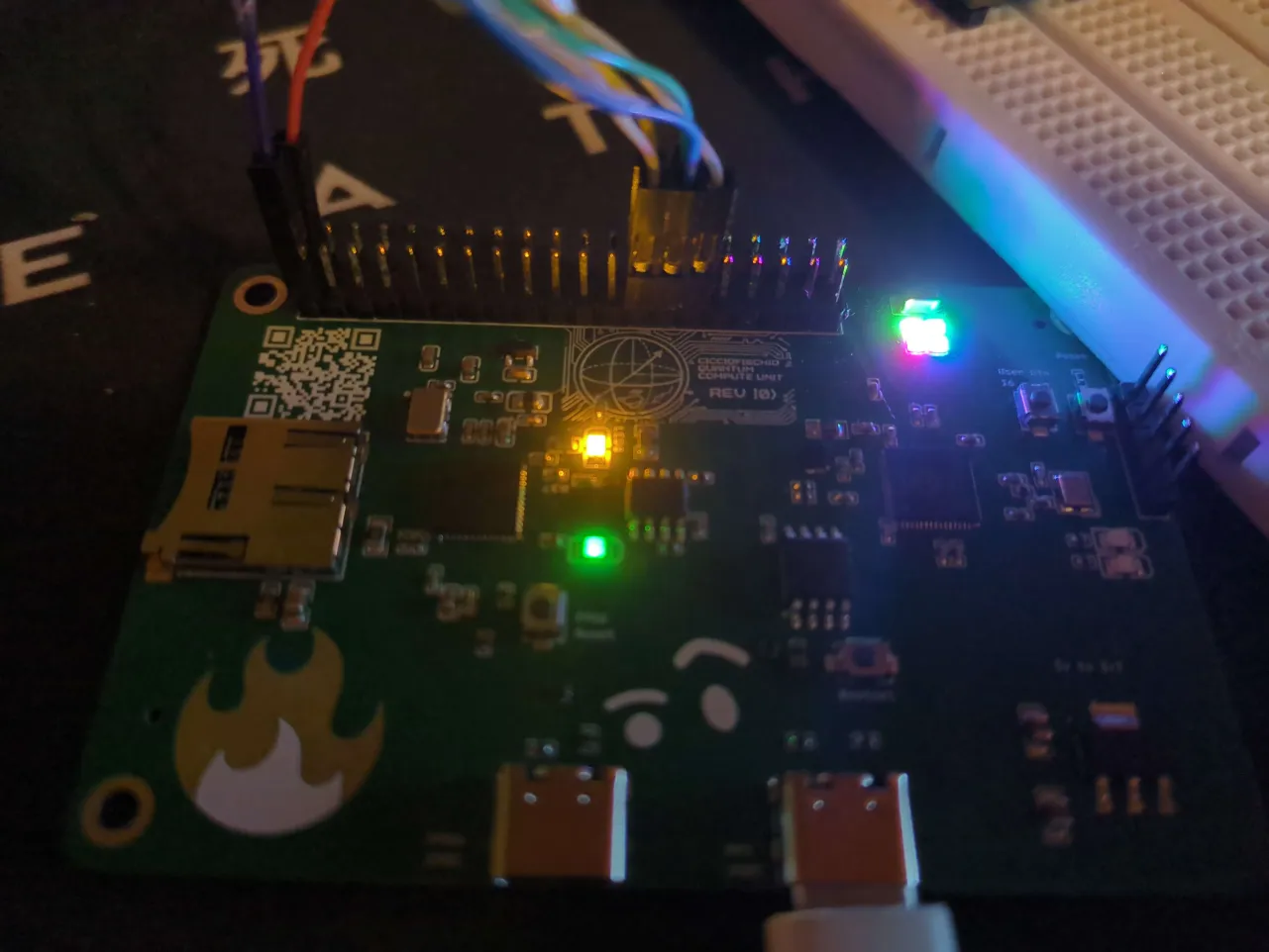
Here I "entangled" 2 qubits to either output 00 or 11!
I made it so an orange light appears when the cpu is in a quantum state, and a green one when it's deterministic.


If you want to try it out, there's the full code on the github page, with the flasher, python UART shell for the rp2350 side, and the fpga code, with a makefile and nix-shell, in case you need it.
Oh btw here are the neopixels working!

Hit me up on slack if you're trying to reproduce my setup or want to make a board like mine and need some help!
John Meshtastic 🚀
added to the journal ago
Blinkmaxxing
Hii, I received a package a few days ago and tried the onboard RP2350 with some NeoPixel code,
firePI neopixel demo
I then tried sending some bits back and forth with the FPGA after not being able to figure out how to make it work for a while.
I also made my own iCE40 flasher, utilizing an external Raspberry Pi Pico (thanks to ChatGPT for the SPI instructions for the flash chip).
I made my own Verilog shell and Makefiles, and made a small blinky program.
(This is my first time writing Verilog for an FPGA!)

 CAN ⚡🚀
approved FirePI ago
CAN ⚡🚀
approved FirePI ago
Tier approved: 2
Grant approved: $146.00
Nice Project
John Meshtastic 🚀
submitted FirePI for ship review ago
John Meshtastic 🚀
added to the journal ago
Final touches

Added mounting holes, I also added a user-button and a few LEDs, switched the old oscillator for a new one (a bit bigger, is a bit better, and also lowers my pcb price).
 NotARoomba 🚀
requested changes for FirePI ago
NotARoomba 🚀
requested changes for FirePI ago
Please try to BOM optimize, that 50mHz crystal can be found for cheaper (C37634189)!
John Meshtastic 🚀
submitted FirePI for ship review ago
 Iamalive 🚀
requested changes for FirePI ago
Iamalive 🚀
requested changes for FirePI ago
Please change your shipping method to global standard direct line and resubmit your shop cart screenshots.
John Meshtastic 🚀
submitted FirePI for ship review ago
 Jay ⚡🚀
requested changes for FirePI ago
Jay ⚡🚀
requested changes for FirePI ago
Go to edit and change to im not following a toutorial or smth as rn this is a hackpad lol
John Meshtastic 🚀
submitted FirePI for ship review ago
 technical_.
requested changes for FirePI ago
technical_.
requested changes for FirePI ago
Extreme use of extended parts for PCBA BOM.
John Meshtastic 🚀
submitted FirePI for ship review ago
technical_.
requested changes for FirePI ago
Please show the full JLCPCB parts list. In addition please go to the final checkout page, so that your duties and customs amount is shown, so that you will not have to wait for a top up/adjustment to your grant!
John Meshtastic 🚀
added to the journal ago
smol update

Fellow readers, we have reached the end, wanted to show you a final pcb screenshot of the wiring, I routed cdone and reset pins out to the headers to be able to program it.
Here follow the rest of the pcb stackup


John Meshtastic 🚀
submitted FirePI for ship review ago
John Meshtastic 🚀
added to the journal ago
The end?

Hi fellow readers, today I added 4 small neopixels on the top-right of my board, fixed some of my extremely janky routing for the headers, added some debug headers for the rp2350 and a button to reset the ice40.
I am most likely finished with this board, just needs some polishing and some silkscreen art :)
John Meshtastic 🚀
added to the journal ago
Routing session #2

Re-did the wiring of some of my components, added routing to the headers
I have yet to find the use for 10 pins
also to add is a nice reset button for the fpga and maybe a programming port
John Meshtastic 🚀
added to the journal ago
Routed?
Today I changed switched of my capacitors to be 0402, I also placed the components on the pcb and routed them, for the most part.
I also decided I will use a 4 layer board with Signal-GND-3v3?-Signal layout.
I have a few doubts if I have positioned the inductors for the rp2350 regulator correctly
Did some of the work in class because I was bored =D

John Meshtastic 🚀
added to the journal ago
Habemus schematic!
INSANE rp2350 && ice40 schematic speedrunning session
Just mostly need to get the 40-pin connector in-place
I still have to find the perfect ferrite bead


I also need to add an SPI and UART connection between the rp2350 and the ice40.
By the way, you might be wondering what are those strangely-routed USB and USBc female ports are for, and I will be using those to see if I can make my own TCP/IP stack on the fpga, as a nice side-quest.
John Meshtastic 🚀
added to the journal ago
Started making the Schematic
Hello, World!
I settled down to a ICE40UP5K-SG48I since it has a QFN package and an OK number of LUTs
Found a crystal suitable for the fpga, and started building the power rails.
I also tried making a power supply filter, but I can't seem to add ferrite beads to the schematic (I'm using Easyeda Pro).

Note that the voltage regulators are still to be chosen, since I want to power an rp2350 on the same board too.
John Meshtastic 🚀
started FirePI ago
10/5/2025 11 AM - Started making the Schematic
Hello, World!
I settled down to a ICE40UP5K-SG48I since it has a QFN package and an OK number of LUTs
Found a crystal suitable for the fpga, and started building the power rails.
I also tried making a power supply filter, but I can't seem to add ferrite beads to the schematic (I'm using Easyeda Pro).
Note that the voltage regulators are still to be chosen, since I want to power an rp2350 on the same board too.
10/5/2025 9 PM - Habemus schematic!
INSANE rp2350 && ice40 schematic speedrunning session
Just mostly need to get the 40-pin connector in-place
I still have to find the perfect ferrite bead
I also need to add an SPI and UART connection between the rp2350 and the ice40.
By the way, you might be wondering what are those strangely-routed USB and USBc female ports are for, and I will be using those to see if I can make my own TCP/IP stack on the fpga, as a nice side-quest.
10/21/2025 - Routed?
Today I changed switched of my capacitors to be 0402, I also placed the components on the pcb and routed them, for the most part.
I also decided I will use a 4 layer board with Signal-GND-3v3?-Signal layout.
I have a few doubts if I have positioned the inductors for the rp2350 regulator correctly
Did some of the work in class because I was bored =D
10/26/2025 - Routing session #2
Re-did the wiring of some of my components, added routing to the headers
I have yet to find the use for 10 pins
also to add is a nice reset button for the fpga and maybe a programming port
10/30/2025 - The end?
Hi fellow readers, today I added 4 small neopixels on the top-right of my board, fixed some of my extremely janky routing for the headers, added some debug headers for the rp2350 and a button to reset the ice40.
I am most likely finished with this board, just needs some polishing and some silkscreen art :)
11/3/2025 - smol update
Fellow readers, we have reached the end, wanted to show you a final pcb screenshot of the wiring, I routed cdone and reset pins out to the headers to be able to program it.
Here follow the rest of the pcb stackup
11/22/2025 - Final touches
Added mounting holes, I also added a user-button and a few LEDs, switched the old oscillator for a new one (a bit bigger, is a bit better, and also lowers my pcb price).
12/14/2025 - Blinkmaxxing
Hii, I received a package a few days ago and tried the onboard RP2350 with some NeoPixel code,
firePI neopixel demo
I then tried sending some bits back and forth with the FPGA after not being able to figure out how to make it work for a while.
I also made my own iCE40 flasher, utilizing an external Raspberry Pi Pico (thanks to ChatGPT for the SPI instructions for the flash chip).
I made my own Verilog shell and Makefiles, and made a small blinky program.
(This is my first time writing Verilog for an FPGA!)
12/23/2025 - Quantum maxxing
Hii. So I decided the most reasonable use of an iCE40UP5K was obviously to make a small "quantum emulator”, because it felt badass, and I literally wrote "quantum" on the silkscreen so that felt like the perfect opportunity.
I don't expect full tickets for this devlog, though I really want to show others what I made :)
I made a 2-qubit emulator, with just real amplitudes (for the sake of simplicity), and a bunch of gates.
I used Q2.14 numbers because floating points are inaccurate at low bit counts and high bit ones are really expensive.
You can control it over uart and send commands like: "r"(reset state), "h0/h1"(applies quantum hadamard gate), "c01/c10" (applies CNOT gate given source and target qubit, "m" (to collapse the "wave function" and collect a reading), and lastly "e", used to send the qubit state and """entangle""" it with another board's
Here I "entangled" 2 qubits to either output 00 or 11!
I made it so an orange light appears when the cpu is in a quantum state, and a green one when it's deterministic.
If you want to try it out, there's the full code on the github page, with the flasher, python UART shell for the rp2350 side, and the fpga code, with a makefile and nix-shell, in case you need it.
Oh btw here are the neopixels working!
Hit me up on slack if you're trying to reproduce my setup or want to make a board like mine and need some help!