BECCA Rocket
Big Engine Certification Completion Attempt . This is an amateur high power rocket being build for my L1 certification launch.
Created by
 Parker Rupe
Tier 1
3535 views
44 followers
 aniruddhashukla07
gave kudos to BECCA Rocket ago
aniruddhashukla07
gave kudos to BECCA Rocket ago
badhiya yaar
 random_revilo
gave kudos to BECCA Rocket ago
random_revilo
gave kudos to BECCA Rocket ago
this is cool
 theo.prime
gave kudos to BECCA Rocket ago
theo.prime
gave kudos to BECCA Rocket ago
Good boy
 ebaduk117
gave kudos to BECCA Rocket ago
ebaduk117
gave kudos to BECCA Rocket ago
hiii
 a**an
gave kudos to BECCA Rocket ago
a**an
gave kudos to BECCA Rocket ago
wow i want to become a aerospace engineer when i grow up. Can u suggest any things to do to get started making rockets?
 M.Abdullah
gave kudos to BECCA Rocket ago
M.Abdullah
gave kudos to BECCA Rocket ago
This is insaneeee
Parker Rupe
added to the journal ago
An Update - Full Progress Check
Alright. It’s been a while since an update. Basically, I moved to a new house. That took up all my free time and was not fun, to say the least. But I am back now and have a cooler space in the new house as my bedroom has counters.
Things remaining for the build:
Sand everything
Make bulkheads
Install fin can in aft body tube
Paint
Things are going quite well and I am really enjoying this build.
I also did 3 hours of sanding on the fin can so now the fins are ready for primer and paint.


Parker Rupe
added to the journal ago
New Eye Bolts and Fancy Sanding Block thingies
Okay so, been working on sanding stuff and ended up buying some fancy foam sandpaper block things. Are they actually fancy? No, they're pretty cheap tbh. But they're way more comfortable to hold and they can absorb water for wet sanding so win-win.

I also sanded the fin can a fair bit, but that was before the foam blocks. It now needs another coat of epoxy, but I want to do that after full fin can assembly, which requires epoxying in the upper puck that holds the eye bolts. I might print a little retaining thingy that gets epoxied in above the puck and is basically just a hollow tube with a lip on the bottom, that lip resting on the puck. That way when it gets yanked on by recovery forces there is more epoxy surface area holding it in place.

This is the fin can after sanding. I used the epoxy to fill in gaps/layer lines and then sanded smooth. This will increase interlayer adhesion and provide a more aerodynamic surface finish. I mostly sanded the fins as those are the only exposed parts.

I ended up buying new eye bolts with my own money as the others were slightly too small. I am working on a refund for those other ones but... it isn't looking good. These will work though.
Oh! I also got some radio trackers.

Each one of these can beep out a signal at 440mhz, which I can use to find the rocket by having a radio and essentially walking in the direction that the beeps get louder. I paid for these myself, but they are designed by a wonderful rocketry enthusiast named ElvinC https://github.com/ElvinC/rocketbeacon.
They still need battery leads and wire whip antennas but thats the gist of it.
Hours counted here are just sanding as that was most of the word - the rest is just updates! I have been doing some sanding on the tubing and coupler but those have very minimal progress so I didn't want to share quite yet. Coming soon though!
 Sasha
gave kudos to BECCA Rocket ago
Sasha
gave kudos to BECCA Rocket ago
Dude, I beg you, add a camera to film the flight on this rocket, I love this project
Parker Rupe
added to the journal ago
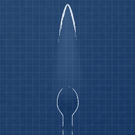
Fin Slot Cutting Jig
Needed to design a simple jig to cut the fin slots. Unfortunately there is no way for me to avoid using supports on this.


The bottom of the tube slots in and then I can cut it with an xacto. If that doesn't work then I will be marking it and cutting it with a dremel.
The rectangular cutouts are the fin slots, while the elipses are just for material savings.
Parker Rupe
added to the journal ago
Making toobs
Sorry for the delay. My whole rocket got locked in my school workshop over Christmas break. But we’re back !!
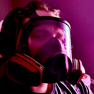
Today I took my main frame tubes (and a coupler) off the mandrels, cut the ends using a miter saw, and started sanding. Because fiberglass is nasty I did this all with a full face respirator, heavy duty gloves, heavy duty dust extraction (240v cyclone dust vacuum with tubes routed all throughout the workshop), and soaked everything in water to manage dust. As you can imagine that made it take a bit.

There’s me with all my gear.


 yugumasudhan
gave kudos to BECCA Rocket ago
yugumasudhan
gave kudos to BECCA Rocket ago
love it
 a4aumshah
gave kudos to BECCA Rocket ago
a4aumshah
gave kudos to BECCA Rocket ago
yo NAR JHPR or tripoli
Parker Rupe
added to the journal ago
Quick Recap of Printed Parts (forgot to do this earlier)
Printing everything took a few weeks and a couple attempts, and total post processing time was right about 3.5 hours. Sanding, removing brims, troubleshooting, etc.


All parts are PA6-GF from Sunlu, which is sooo lovely to work with. Prints like a dream, crazy strong, super pretty. Side note - Yes, I am sponsored. But, I have zero obligation to say positive things about this filament. I actually used to pay for this stuff myself, AND the college rocketry team I am a part of pays for it themselves too! No sponsorship on that one, and they've been doing it since before I joined. It's just... awesome. I highly recommend people try it.
I actually printed two fin cans, one with the earlier smaller fins, which I ended up using to test fin breakoff strength. Not only did the fin can survive being thrown across the room multiple times (as hard as I could manage), but breaking off the fin took around 150 pounds of force! The new bigger fin can can actually support my whole body weight spread across two fins, which currently is about 255lbs!! I don't have photos of that because it was really sketchy.
Old Can:

Parker Rupe
added to the journal ago
Body Tube Work! Part 2
This time was applying the epoxy! Which was so, so messy, and I went through 6 pairs of gloves! 6!
I also realized I needed to do a fiberglass layup on the AV bay coupler and I decided to coat the fin can and nose cone in epoxy in an attempt to improve interlayer adhesion by bonding together the layer lines. It also means less sanding work to get it smooth.
So here are the two tubes AV bay coupler, fin can, and nose cone:


And a bit closer up of the tubes:

These will be curing over the weekend until I can come back to the school shop monday!
Also once again, this took way longer than expected, and I had to work in a full face respirator the whole time, as I am sensitive to epoxy.
Parker Rupe
added to the journal ago
Body Tube Work! Part 1
Some of my orders arrived! I got cardboard body tubes and fiberglass sleeving to layup onto them. This is called "glassing" the part and I will be refering to it as such from now on.

I started with the shorter section, the fore (upper) airframe. This is an 18" cardboard tube and one layer of medium weight fiberglass from Soller. I used a PVC pipe through the tube as a sort of tensioning rod. That way I could use zip ties to pull the fiberglass sleeve tight onto the cardboard.

This is the longer section, the aft (lower) airframe. This is two cardboard tubes, one 18 inches and one roughly 7.85 inch section. The tubes shipped in 18" sections, so one is cut down and one is not cut. These are joined by a printed coupler I epoxied in place. Most of the structural load should go through the fiberglass sleeve, which is not split along the length of the tube at all, so I felt comfortable using a printed piece. Did I get photos of that? No, I forgot. But here it is in CAD, and once the tube is finished I will take some photos of the coupler epoxied in place.

Prep took so long dude. So long.
 octo
gave kudos to BECCA Rocket ago
octo
gave kudos to BECCA Rocket ago
Dayumn it is sick
 nimit ⚡🚀
gave kudos to BECCA Rocket ago
nimit ⚡🚀
gave kudos to BECCA Rocket ago
hungry for update
 aedurstewitz
gave kudos to BECCA Rocket ago
aedurstewitz
gave kudos to BECCA Rocket ago
Awesome! Also what is "L1 cert launch?"
 Codecooker Mintz
gave kudos to BECCA Rocket ago
Codecooker Mintz
gave kudos to BECCA Rocket ago
cool
Parker Rupe
added to the journal ago
Ordered all the grant parts!
I ordered everything that the grant is paying for, which is the rocket itself (save for paint), no flammable/explosives. Which is completely fair ! It took about an hour because some of the sites were being really annoying and confusing about the billing address and one site was freaking out with their shipping calculator but I called them and we figured it out. Yay ! 
 Charles
gave kudos to BECCA Rocket ago
Charles
gave kudos to BECCA Rocket ago
Insane
 CAN ⚡🚀
approved BECCA Rocket ago
CAN ⚡🚀
approved BECCA Rocket ago
Tier approved: 1
Grant approved: $323.00
Insane project
a**69
gave kudos to BECCA Rocket ago
damn son
 lowpolyphosphorus
gave kudos to BECCA Rocket ago
lowpolyphosphorus
gave kudos to BECCA Rocket ago
nerd
 NotARoomba 🚀
gave kudos to BECCA Rocket ago
NotARoomba 🚀
gave kudos to BECCA Rocket ago
nerd
 Tanuki ⚡🚀
gave kudos to BECCA Rocket ago
Tanuki ⚡🚀
gave kudos to BECCA Rocket ago
nerd
 Frog
gave kudos to BECCA Rocket ago
Frog
gave kudos to BECCA Rocket ago
nerd
 Raygen Rupe 🚀
gave kudos to BECCA Rocket ago
Raygen Rupe 🚀
gave kudos to BECCA Rocket ago
nerd
Parker Rupe
submitted BECCA Rocket for ship review ago
Tanuki ⚡🚀
requested changes for BECCA Rocket ago
Looking good! GL on that certificate :)
Parker Rupe
submitted BECCA Rocket for ship review ago
Parker Rupe
added to the journal ago
Resubmit with New BOM, New Journal, and New Fancy Render
I put a lot of effort into redoing this to match the higher quality standard that CAN expects of me. I also had to give a school presentation on this project, which was the main reason for the new render actually. It's a really cool render though! And was only like... kind of done stupidly?
Like, great render!!

But the way I pulled it off was a bit... quirky...

That flame texture took 3 hours. Dead serious. It was so annoying and fusion was definitely not the right tool for this but man I just really hate blender.
Parker Rupe
added to the journal ago
A little bit of hyper obsession
Okay so. I discovered that there is a public engineering drawing of the solid rocket engine I am using - yet there was no 3D model.
There is now a 3D model. Not only did I take the time to match it to the drawing identically, but I even took the time to material match every component to the point of the model being within roughly 2% of the real mass. 2%. Once I fire a motor I will cut it vertically down the middle and verify all of my dimensions.


And of course, that makes my cross section look sick as hell.

This likely took more than 6 hours but I can't accurately say how much it actually took, so I am gonna call it 6 hours. It did make me pull an all nighter though...
Parker Rupe
added to the journal ago
Grant denied
So there was a big mess in rocketry stuff due to misunderstandings/miscommunications on safety and design expectations. It took a while to work out, but for a while I thought this would have to be tier 2 unless I had a custom flight controller (which I cannot do for a certification flight). It got worked out though! I just had to overhaul my journal, which has taken about 3 hours.

Parker Rupe
added to the journal ago
Write BOM, polish repository, submit for grant.
I spent a couple hours writing out my BOM and cost optimizing it, as well as organizing the repository files and making everything look nice. I made the bom in Google Sheets and all renders are from Fusion.

Parker Rupe
added to the journal ago
Back to Aesthetics!
I decided to take a bunch of renders for promotional instagram material (gotta make my sponsor happy), sharing with my teachers, and for the github repository. This was also when I added my decals.


The odd clipping black lines are internal geometry such as couplers. Fusion doesn't like rendering thin walls.
Parker Rupe
added to the journal ago
Fin Can Redesign Part 2
Now that I had optimized the new fins in Openrocket, I had to model them in Fusion 360.
I follow NACA airfoil guidelines for a very neutral airfoil. Max fin thickness is at 30% of the chord length and defined minimum/maximum radii for the leading and trailing edge so that it is printable.

Specifically this one, NACA 0015.

New bigger fins
AND

New internal support structure for the motor. Being able to define the voids myself saves more material than slicer auto infill generation.
Parker Rupe
added to the journal ago
Fin Can Redesign Part 1
So, I had to go back to my openrocket sim. My fins had too low of a span (how far it stuck out from the rocket) and too short of a root cord (the base of the fin, where it attaches to the rocket. I also wanted to increase the fillets just in case something wonky happens, I want the fins to stay on.
Old Fins

New Fins

Pretty big difference! This mistake was pointed out to me by some of the members of the r/rocketry discord that I met, who have a lot more experience than I do. I am thankful for them.
Parker Rupe
added to the journal ago
Aesthetics !
At this point, I decided to address the appearance of the rocket. While I already sort of had a color scheme, it wasn't finalized, nor had I planned any decals. I messed around with physical sketches, asked friends, even tried to use blender (never made progress on blender. I hate blender.)

So I took that render, which took a while to get right. And then I went to do decals - I want one with the rocket name and one with my personal sponsor, Sunlu.
However, this was when I found out my fins were too small. Which means... fin can redesign!
Parker Rupe
added to the journal ago
Recovery Attachment Points
I spent a while researching and planning how I would attach the sections of the rocket to the parachutes and shock cords. There are many methods, including epoxying the cord to the airframe. I did not like that option. So, for the lower section, I put two eye bolts in the fin can, allowing for a Y-harness to be attached, distributing the force across the two eye bolts so I don't have to deal with fitting larger ones.
For the upper section, since my nosecone is 3D printed, I just included a bulky channell that the cord will be fed through and then tied off. The nose cone is permenantly affixed to the upper airframe section.


Parker Rupe
added to the journal ago
The Actual AV Part of the AV Bay

I chose to run a featherweight blue jay and rrc2+ altimeter for my parachute deployment electronics, as well as a custom gps tracking setup using a particle boron and adafruit featherwing gps thingy that I had sitting on a shelf.
The mount I designed is pretty simple and non structural besides holding the electronics. Instead, all force goes through the 3 threaded steel rods, which is significantly overrated (but that is ideal). There's no dedicated battery mounting, but rather just a bunch of slats for zip tying them on, as that allows for better flexibility (lipo batteries are so fragile D:).
Currently, the plan for the charge cannons is to 3d print a threaded cap, as the body of the cannons are coupling nuts (long internally threaded cylinders). I just have to make them very thin so that they get effectively vaporized by the charge rather than shot off like a bullet, straight into my parachutes.
Parker Rupe
added to the journal ago
Began Work on Main Coupler/AV Bay
So, in the middle of the rocket there is a black band, called a switch band. Because your power switch access goes in it! Thus, this notates where the AV bay is, and in my case, the main coupler. In the section of the rocket above the av bay is the main parachute and in the section below the av bay is the drogue parachute. The drogue deploys at apogee to allow for slowed descent, but still fast enough to not drift far, and then the main parachute deploys at a lower altitude. These parachutes are deployed via black powder charges. There are a few methods of charge containment, but I chose to do what is called "charge cannons". Long metal tubes with black powder in them, allowing for the black powder to pressurize and fullly ignite inside the cannon regardless of altitude. It also is a much more elegant solution that the standard for L1 rockets - a rubber glove tip filled with gun powder. I'm not kidding.

There are also U bolts for parachute and shock cord attachment.
Parker Rupe
added to the journal ago
Continued CAD Work

I decided to rough out the rest of the rocket. It's really just empty tubes and basic shapes, but it still took a little while to match my sim 1:1. I even took the time to model the two airframe layers, with the cardboard base and fiberglass sleeving.
Parker Rupe
added to the journal ago
Began Cad Design
I decided to start the CAD design in fusion 360 as I felt pretty comfortable with where the openrocket sim was at.


I know I said that common protocol is to start from the top and work down. However, the fin can was by far the most complex part of this design, so I chose to start with that.
Fin cans typically just slide over the air frame (assuming you use a fin can). I didn't really like the way it made a bump due to the changing diameter. So, I thought it could be cool if the airframe tube slotted over the fin can. I think it looks really nice!
Parker Rupe
added to the journal ago
Improved Openrocket Sim
I spent about 5 hours selecting my motor, fin geometry, and finalizing length of the rocket. I also adjusted parachute selection to account for the new weight total.

I actually also spent some time investigating what it would be like if I made a much skinnier but taller rocket. While it would have been interesting, it's not super practical for a certification flight.
I didn't get many photos of the long rocket, unfortunately. I repurposed the sim for a potential future project almost immediately and didn't share with anyone.
I chose the aerotech I500 engine and a dual deploy parachute setup. Both of these are largely intended for high performance rockets - but because I wanted to get the experience of building a big rocket, I also chose to practice the more advanced techniques required for those processes.
CAN ⚡🚀
requested changes for BECCA Rocket ago
Could you make your own Altimeter or flight controller? Also, please split your journal entrries more.
Parker Rupe
submitted BECCA Rocket for ship review ago
Parker Rupe
added to the journal ago
Began main design in OpenRocket!
October 9, 2025
Openrocket is a rocketry simulation software useful for getting overall layout, fin size/geometry, motor selection, etc.

Common practice is to start with the top of the rocket and work backwards, so that's what I did. This took about 4 hours as I had to research and select options for nosecone geometry, couplers, and where I want the rocket sections to seperate for parachute deployment.
Parker Rupe
started BECCA Rocket ago
10/12/2025 - Began main design in OpenRocket!
October 9, 2025
Openrocket is a rocketry simulation software useful for getting overall layout, fin size/geometry, motor selection, etc.
Common practice is to start with the top of the rocket and work backwards, so that's what I did. This took about 4 hours as I had to research and select options for nosecone geometry, couplers, and where I want the rocket sections to seperate for parachute deployment.
12/5/2025 8:33 AM - Improved Openrocket Sim
I spent about 5 hours selecting my motor, fin geometry, and finalizing length of the rocket. I also adjusted parachute selection to account for the new weight total.
I actually also spent some time investigating what it would be like if I made a much skinnier but taller rocket. While it would have been interesting, it's not super practical for a certification flight.
I didn't get many photos of the long rocket, unfortunately. I repurposed the sim for a potential future project almost immediately and didn't share with anyone.
I chose the aerotech I500 engine and a dual deploy parachute setup. Both of these are largely intended for high performance rockets - but because I wanted to get the experience of building a big rocket, I also chose to practice the more advanced techniques required for those processes.
12/5/2025 8:37 AM - Began Cad Design
I decided to start the CAD design in fusion 360 as I felt pretty comfortable with where the openrocket sim was at.
I know I said that common protocol is to start from the top and work down. However, the fin can was by far the most complex part of this design, so I chose to start with that.
Fin cans typically just slide over the air frame (assuming you use a fin can). I didn't really like the way it made a bump due to the changing diameter. So, I thought it could be cool if the airframe tube slotted over the fin can. I think it looks really nice!
12/5/2025 8:41 AM - Continued CAD Work
I decided to rough out the rest of the rocket. It's really just empty tubes and basic shapes, but it still took a little while to match my sim 1:1. I even took the time to model the two airframe layers, with the cardboard base and fiberglass sleeving.
12/5/2025 8:48 AM - Began Work on Main Coupler/AV Bay
So, in the middle of the rocket there is a black band, called a switch band. Because your power switch access goes in it! Thus, this notates where the AV bay is, and in my case, the main coupler. In the section of the rocket above the av bay is the main parachute and in the section below the av bay is the drogue parachute. The drogue deploys at apogee to allow for slowed descent, but still fast enough to not drift far, and then the main parachute deploys at a lower altitude. These parachutes are deployed via black powder charges. There are a few methods of charge containment, but I chose to do what is called "charge cannons". Long metal tubes with black powder in them, allowing for the black powder to pressurize and fullly ignite inside the cannon regardless of altitude. It also is a much more elegant solution that the standard for L1 rockets - a rubber glove tip filled with gun powder. I'm not kidding.
There are also U bolts for parachute and shock cord attachment.
12/5/2025 9:08 AM - The Actual AV Part of the AV Bay
I chose to run a featherweight blue jay and rrc2+ altimeter for my parachute deployment electronics, as well as a custom gps tracking setup using a particle boron and adafruit featherwing gps thingy that I had sitting on a shelf.
The mount I designed is pretty simple and non structural besides holding the electronics. Instead, all force goes through the 3 threaded steel rods, which is significantly overrated (but that is ideal). There's no dedicated battery mounting, but rather just a bunch of slats for zip tying them on, as that allows for better flexibility (lipo batteries are so fragile D:).
Currently, the plan for the charge cannons is to 3d print a threaded cap, as the body of the cannons are coupling nuts (long internally threaded cylinders). I just have to make them very thin so that they get effectively vaporized by the charge rather than shot off like a bullet, straight into my parachutes.
12/5/2025 9:14 AM - Recovery Attachment Points
I spent a while researching and planning how I would attach the sections of the rocket to the parachutes and shock cords. There are many methods, including epoxying the cord to the airframe. I did not like that option. So, for the lower section, I put two eye bolts in the fin can, allowing for a Y-harness to be attached, distributing the force across the two eye bolts so I don't have to deal with fitting larger ones.
For the upper section, since my nosecone is 3D printed, I just included a bulky channell that the cord will be fed through and then tied off. The nose cone is permenantly affixed to the upper airframe section.
12/5/2025 9:21 AM - Aesthetics !
At this point, I decided to address the appearance of the rocket. While I already sort of had a color scheme, it wasn't finalized, nor had I planned any decals. I messed around with physical sketches, asked friends, even tried to use blender (never made progress on blender. I hate blender.)
So I took that render, which took a while to get right. And then I went to do decals - I want one with the rocket name and one with my personal sponsor, Sunlu.
However, this was when I found out my fins were too small. Which means... fin can redesign!
12/5/2025 9:24 AM - Fin Can Redesign Part 1
So, I had to go back to my openrocket sim. My fins had too low of a span (how far it stuck out from the rocket) and too short of a root cord (the base of the fin, where it attaches to the rocket. I also wanted to increase the fillets just in case something wonky happens, I want the fins to stay on.
Old Fins
New Fins
Pretty big difference! This mistake was pointed out to me by some of the members of the r/rocketry discord that I met, who have a lot more experience than I do. I am thankful for them.
12/5/2025 9:28 AM - Fin Can Redesign Part 2
Now that I had optimized the new fins in Openrocket, I had to model them in Fusion 360.
I follow NACA airfoil guidelines for a very neutral airfoil. Max fin thickness is at 30% of the chord length and defined minimum/maximum radii for the leading and trailing edge so that it is printable.
Specifically this one, NACA 0015.
New bigger fins
AND
New internal support structure for the motor. Being able to define the voids myself saves more material than slicer auto infill generation.
12/5/2025 9:31 AM - Back to Aesthetics!
I decided to take a bunch of renders for promotional instagram material (gotta make my sponsor happy), sharing with my teachers, and for the github repository. This was also when I added my decals.
The odd clipping black lines are internal geometry such as couplers. Fusion doesn't like rendering thin walls.
12/5/2025 9:32 AM - Write BOM, polish repository, submit for grant.
I spent a couple hours writing out my BOM and cost optimizing it, as well as organizing the repository files and making everything look nice. I made the bom in Google Sheets and all renders are from Fusion.
12/5/2025 9:35 AM - Grant denied
So there was a big mess in rocketry stuff due to misunderstandings/miscommunications on safety and design expectations. It took a while to work out, but for a while I thought this would have to be tier 2 unless I had a custom flight controller (which I cannot do for a certification flight). It got worked out though! I just had to overhaul my journal, which has taken about 3 hours.
12/5/2025 9:38 AM - A little bit of hyper obsession
Okay so. I discovered that there is a public engineering drawing of the solid rocket engine I am using - yet there was no 3D model.
There is now a 3D model. Not only did I take the time to match it to the drawing identically, but I even took the time to material match every component to the point of the model being within roughly 2% of the real mass. 2%. Once I fire a motor I will cut it vertically down the middle and verify all of my dimensions.
And of course, that makes my cross section look sick as hell.
This likely took more than 6 hours but I can't accurately say how much it actually took, so I am gonna call it 6 hours. It did make me pull an all nighter though...
12/5/2025 9:42 AM - Resubmit with New BOM, New Journal, and New Fancy Render
I put a lot of effort into redoing this to match the higher quality standard that CAN expects of me. I also had to give a school presentation on this project, which was the main reason for the new render actually. It's a really cool render though! And was only like... kind of done stupidly?
Like, great render!!
But the way I pulled it off was a bit... quirky...
That flame texture took 3 hours. Dead serious. It was so annoying and fusion was definitely not the right tool for this but man I just really hate blender.
12/11/2025 - Ordered all the grant parts!
I ordered everything that the grant is paying for, which is the rocket itself (save for paint), no flammable/explosives. Which is completely fair ! It took about an hour because some of the sites were being really annoying and confusing about the billing address and one site was freaking out with their shipping calculator but I called them and we figured it out. Yay !
12/20/2025 12:24 AM - Body Tube Work! Part 1
Some of my orders arrived! I got cardboard body tubes and fiberglass sleeving to layup onto them. This is called "glassing" the part and I will be refering to it as such from now on.
I started with the shorter section, the fore (upper) airframe. This is an 18" cardboard tube and one layer of medium weight fiberglass from Soller. I used a PVC pipe through the tube as a sort of tensioning rod. That way I could use zip ties to pull the fiberglass sleeve tight onto the cardboard.
This is the longer section, the aft (lower) airframe. This is two cardboard tubes, one 18 inches and one roughly 7.85 inch section. The tubes shipped in 18" sections, so one is cut down and one is not cut. These are joined by a printed coupler I epoxied in place. Most of the structural load should go through the fiberglass sleeve, which is not split along the length of the tube at all, so I felt comfortable using a printed piece. Did I get photos of that? No, I forgot. But here it is in CAD, and once the tube is finished I will take some photos of the coupler epoxied in place.
Prep took so long dude. So long.
12/20/2025 12:36 AM - Body Tube Work! Part 2
This time was applying the epoxy! Which was so, so messy, and I went through 6 pairs of gloves! 6!
I also realized I needed to do a fiberglass layup on the AV bay coupler and I decided to coat the fin can and nose cone in epoxy in an attempt to improve interlayer adhesion by bonding together the layer lines. It also means less sanding work to get it smooth.
So here are the two tubes AV bay coupler, fin can, and nose cone:
And a bit closer up of the tubes:
These will be curing over the weekend until I can come back to the school shop monday!
Also once again, this took way longer than expected, and I had to work in a full face respirator the whole time, as I am sensitive to epoxy.
12/20/2025 12:43 AM - Quick Recap of Printed Parts (forgot to do this earlier)
Printing everything took a few weeks and a couple attempts, and total post processing time was right about 3.5 hours. Sanding, removing brims, troubleshooting, etc.
All parts are PA6-GF from Sunlu, which is sooo lovely to work with. Prints like a dream, crazy strong, super pretty. Side note - Yes, I am sponsored. But, I have zero obligation to say positive things about this filament. I actually used to pay for this stuff myself, AND the college rocketry team I am a part of pays for it themselves too! No sponsorship on that one, and they've been doing it since before I joined. It's just... awesome. I highly recommend people try it.
I actually printed two fin cans, one with the earlier smaller fins, which I ended up using to test fin breakoff strength. Not only did the fin can survive being thrown across the room multiple times (as hard as I could manage), but breaking off the fin took around 150 pounds of force! The new bigger fin can can actually support my whole body weight spread across two fins, which currently is about 255lbs!! I don't have photos of that because it was really sketchy.
Old Can:
1/6/2026 - Making toobs
Sorry for the delay. My whole rocket got locked in my school workshop over Christmas break. But we’re back !!
Today I took my main frame tubes (and a coupler) off the mandrels, cut the ends using a miter saw, and started sanding. Because fiberglass is nasty I did this all with a full face respirator, heavy duty gloves, heavy duty dust extraction (240v cyclone dust vacuum with tubes routed all throughout the workshop), and soaked everything in water to manage dust. As you can imagine that made it take a bit.
There’s me with all my gear.
1/7/2026 - Fin Slot Cutting Jig
Needed to design a simple jig to cut the fin slots. Unfortunately there is no way for me to avoid using supports on this.
The bottom of the tube slots in and then I can cut it with an xacto. If that doesn't work then I will be marking it and cutting it with a dremel.
The rectangular cutouts are the fin slots, while the elipses are just for material savings.
1/16/2026 - New Eye Bolts and Fancy Sanding Block thingies
Okay so, been working on sanding stuff and ended up buying some fancy foam sandpaper block things. Are they actually fancy? No, they're pretty cheap tbh. But they're way more comfortable to hold and they can absorb water for wet sanding so win-win.
I also sanded the fin can a fair bit, but that was before the foam blocks. It now needs another coat of epoxy, but I want to do that after full fin can assembly, which requires epoxying in the upper puck that holds the eye bolts. I might print a little retaining thingy that gets epoxied in above the puck and is basically just a hollow tube with a lip on the bottom, that lip resting on the puck. That way when it gets yanked on by recovery forces there is more epoxy surface area holding it in place.
This is the fin can after sanding. I used the epoxy to fill in gaps/layer lines and then sanded smooth. This will increase interlayer adhesion and provide a more aerodynamic surface finish. I mostly sanded the fins as those are the only exposed parts.
I ended up buying new eye bolts with my own money as the others were slightly too small. I am working on a refund for those other ones but... it isn't looking good. These will work though.
Oh! I also got some radio trackers.
Each one of these can beep out a signal at 440mhz, which I can use to find the rocket by having a radio and essentially walking in the direction that the beeps get louder. I paid for these myself, but they are designed by a wonderful rocketry enthusiast named ElvinC https://github.com/ElvinC/rocketbeacon.
They still need battery leads and wire whip antennas but thats the gist of it.
Hours counted here are just sanding as that was most of the word - the rest is just updates! I have been doing some sanding on the tubing and coupler but those have very minimal progress so I didn't want to share quite yet. Coming soon though!
2/5/2026 - An Update - Full Progress Check
Alright. It’s been a while since an update. Basically, I moved to a new house. That took up all my free time and was not fun, to say the least. But I am back now and have a cooler space in the new house as my bedroom has counters.
Things remaining for the build:
Sand everything
Make bulkheads
Install fin can in aft body tube
Paint
Things are going quite well and I am really enjoying this build.
I also did 3 hours of sanding on the fin can so now the fins are ready for primer and paint.