Nibunkatsu One, a Split Keyboard
My first and very own Split Keyboard! A compact, ergonomic split keyboard designed for everyday typing and programming. Built using the ESP32-S3 microcontroller with KMK firmware, featuring per-key RGB underglow, an OLED display, and a rotary encoder! :D
Created by
 GabiBrawl
Tier 2
63 views
2 followers
 eyal.birger2010
gave kudos to Nibunkatsu One, a Split Keyboard ago
eyal.birger2010
gave kudos to Nibunkatsu One, a Split Keyboard ago
this is really coolllllll. i want to also do a build without a micro controller (like a nice nano or an arduino)...
 m0.hid ⚡
approved Nibunkatsu One, a Split Keyboard ago
m0.hid ⚡
approved Nibunkatsu One, a Split Keyboard ago
Tickets awarded: 263 tickets
Tier: 2
Great work on this keyboard! I love the overall aesthetic of this keyboard - the leds and oled look really cool!
 Ashar
gave kudos to Nibunkatsu One, a Split Keyboard ago
Ashar
gave kudos to Nibunkatsu One, a Split Keyboard ago
Can I talk to you for help?
 vejas 🚀
gave kudos to Nibunkatsu One, a Split Keyboard ago
vejas 🚀
gave kudos to Nibunkatsu One, a Split Keyboard ago
HELLA TUFF GNG 🔥🔥🗣️🗣️
GabiBrawl
submitted Nibunkatsu One, a Split Keyboard for ship review ago
GabiBrawl
added to the journal ago
09/01/26 - Received Final Parts & Finished the Assembly!
The final boxes from AliExpress arrived, so the assembly was concluded on this day!
The process was pretty straight forward:
- open the 100 plastic packets from aliexpress
- sort the components
- soldered the LEDs, then the hotswap sockets and finally the rotary encoder
- then slotted the boards on the 3D prints and manually fixed some minor fitting issues
- plugged everything in, made multiple firmware adjustments and got a functional keyboard!!
More assembly details
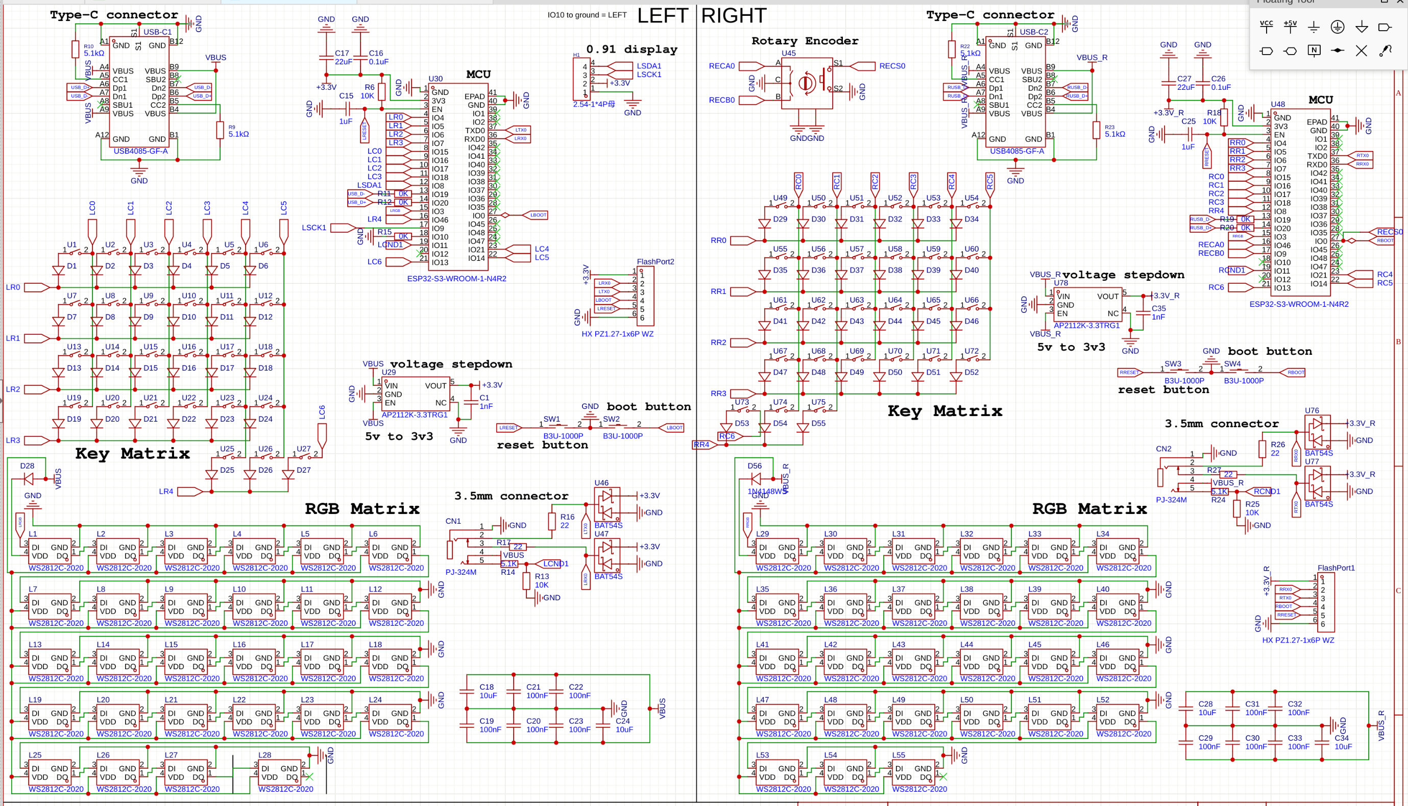
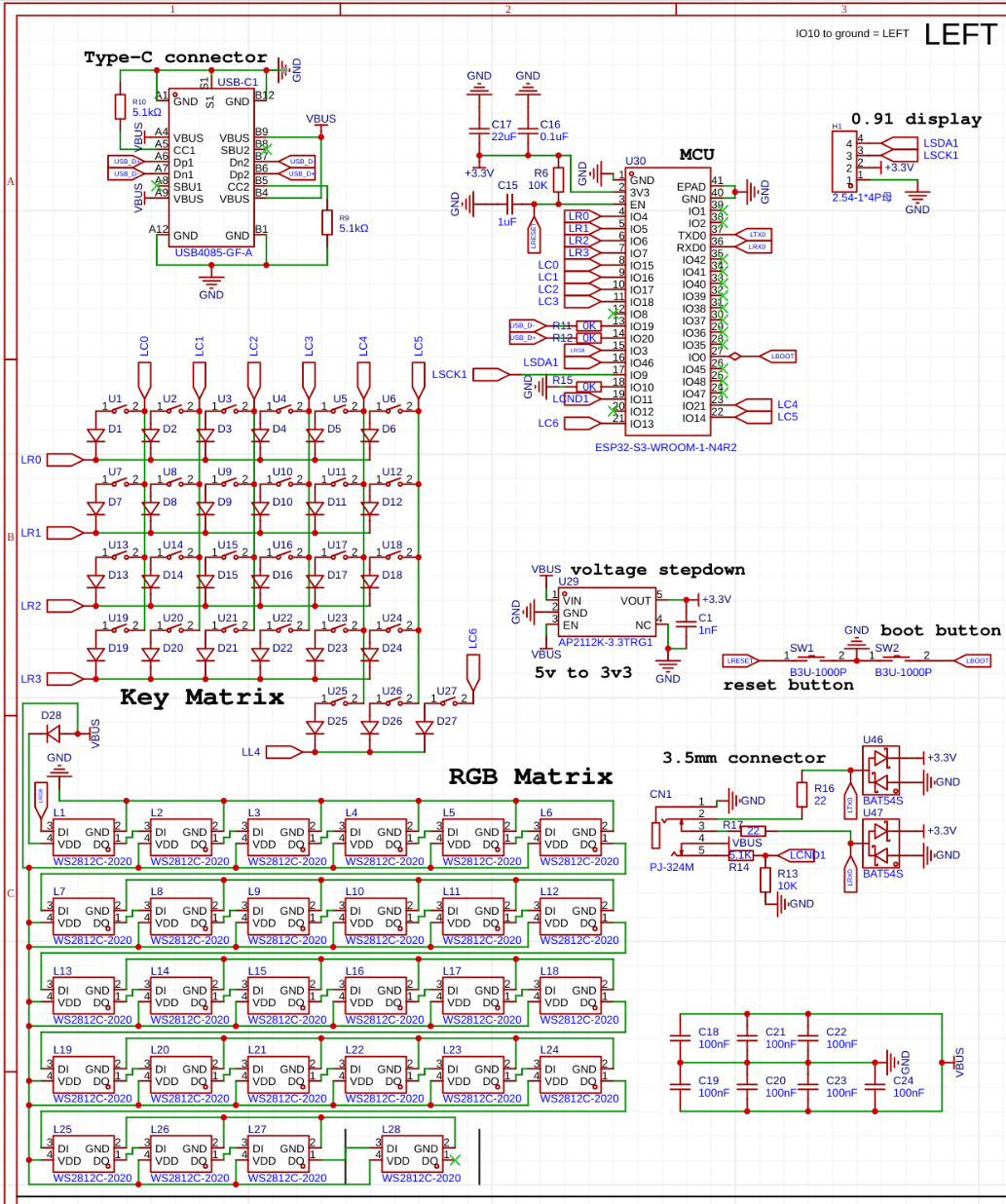
- The first LED in each board hat to be shut off completely. This is due to it being used to boost the signal from 3v3 to 5v. The ESP can only send 3V3 signals through it's GPIO, so the first led is the only one being powered from the 3V3 rail, and all the rest are on the 5V rail. The LEDs in the 3V3 rail can take a 3V3 signal, but the 5V leds require a 5V signal. So to overcome this, we use the first LED to step up the signal voltage, but had to turn it off via firmware so that it doesn't get into power drops when changing color to brighter tones.
- I had to pivot from TRS to ESP-NOW, after realizing that the 3.5mm connector jack was only a 3-pin (TRS) and not a 4-pin (TRRS) as expected so I had to re-code the firmware to use ESP-NOW for wireless communication between the halves. The physical cable is only used for 5V power transmission now.
FINALIZED PICS:


Issues I faced:
I placed the keys too close together, and the keycaps set I ordered doesn't fit >:
I have two fixes for this: for the short term I'll print custom keycaps and use those. For the longer term I'll make new PCBs fixing all issues I faced and order them whenever I have money xD

A whole column of keys on each side doesn't register clicks. I will have to rewire it manually.
GabiBrawl
added to the journal ago
03/01/26 - More coding
Today was dedicated more to some coding refinements and better sync both halves of the keyboard wirelessly via ESP-IDF. Also created a debug menu with info from both sides. the menu shows up when holding IO0 to GND.
I chose the wrong 3.5mm connector. I thought the connector had 5 pins cuz it had 4 contact points and a detection pin, but no. It has 3 pins and 2 detection pins for some reason. So the original plan for both halves to communicate together via the TRRS cable with the TX and RX pins was scrapped in favor of ESP-IDF communication. The 3.5mm connector only powers the right half with 5V and GND.
Multiple optimizations have been made to key scanning, RGB handling and some other things.
GabiBrawl
added to the journal ago
02/01/26 - More soldering, testing and discovery!
The Aliexpress parts arrived today!
I spent some time developing the firmware, soldering the LEDs, the 3.5mm connector, and the hotswap sockets. As with any prototype, a few challenges appeared:
- The first LED in the matrix is currently acting only as a signal amplifier. To stabilize the data for the rest of the chain, I had to keep it turned off. This is a functional workaround for now. For the future I'll add an LED spot only for signal amplification, outside of the matrix.
- I realized I accidentally used a TRS (3-pin) connector instead of a TRRS (4-pin). Since I’m short on pins for wired data, I’ve pivoted: the 3.5mm cable will now only provide power to the secondary half, and I’ll use ESP-NOW for wireless communication between the two sides.
- The switch spacing is a bit too tight, which means my standard keycap set won't fit. My immediate solution is to 3D print custom, more compact keycaps for this specific revision.
Errors are how you learn. I’ve applied lessons from past failures to fix old bugs, even if new ones took their place. I’m still aiming for a "perfectly baked" Nibunkatsu keyboard, so for now, I’ll bridge these gaps to get it functional and prepare for the next board revision!


GabiBrawl
added to the journal ago
01/01/26 - Soldering and coding...
Before anything, Happy new year! :D
The PCB arrived and most components too! I soldered the minimal components to get the ESP32 chip working through the USB port so I could start developing some code. Little did I know that getting the ESP32-S3 N4 would bring nothing but issues... (if you're getting an N4, get at least the N4R2)
My initial plans for the project was to use Circuit Python and KMK, but no builds are available for the N4 apparently. I tried developing in Platformio something then, and oh boy I couldn't get the ESP to boot normally without bootlooping. I spent the whole day troubleshooting and making a semi-custom compiler in Platformio for this chip... (yes Grok Code Fast 1 did most of the heavy lifting here, but I had to research some old solutions that worked in the past but no longer now too)
For now I started development using the Arduino Framework but I will try to move into ESP-IDF instead.
I got the RGB working and some kind of key scanning and basic hid input working.


 CAN ⚡🚀
approved Nibunkatsu One, a Split Keyboard ago
CAN ⚡🚀
approved Nibunkatsu One, a Split Keyboard ago
Tier approved: 2
Grant approved: $203.00
Awesome project
GabiBrawl
submitted Nibunkatsu One, a Split Keyboard for ship review ago
 Iamalive 🚀
requested changes for Nibunkatsu One, a Split Keyboard ago
Iamalive 🚀
requested changes for Nibunkatsu One, a Split Keyboard ago
Please include your shipping prices as cart screenshots as well!
GabiBrawl
added to the journal ago
13/12/25 - Repository organization and fixes
Fixed plenty of things in the repository, and made changes to the BOM and License choice reasoning.
This post will also serve as a fix for the project banner, as I've discovered why it kept being white in spite of all images I added! This is the hero image I used for the github repository of the project.

GabiBrawl
submitted Nibunkatsu One, a Split Keyboard for ship review ago
 zsharpminor ⚡
requested changes for Nibunkatsu One, a Split Keyboard ago
zsharpminor ⚡
requested changes for Nibunkatsu One, a Split Keyboard ago
Please change your shipping on JLCPCB to the cheapest method possible (usually Global Standard Direct Line). If you already have the cheapest method possible, please resubmit, thanks!
GabiBrawl
submitted Nibunkatsu One, a Split Keyboard for ship review ago
 nimit ⚡🚀
requested changes for Nibunkatsu One, a Split Keyboard ago
nimit ⚡🚀
requested changes for Nibunkatsu One, a Split Keyboard ago
Your TRS cable is far too expensive! With the ESP, you can either establish wireless individually on both halves (something like ZMK), or get a cheaper TRS cable! Also, you have 3 different licenses for this project? Could you elaborate? Make sure to also include all the items in your cart screenshots, it seems that some of them are outside.
GabiBrawl
submitted Nibunkatsu One, a Split Keyboard for ship review ago
GabiBrawl
added to the journal ago
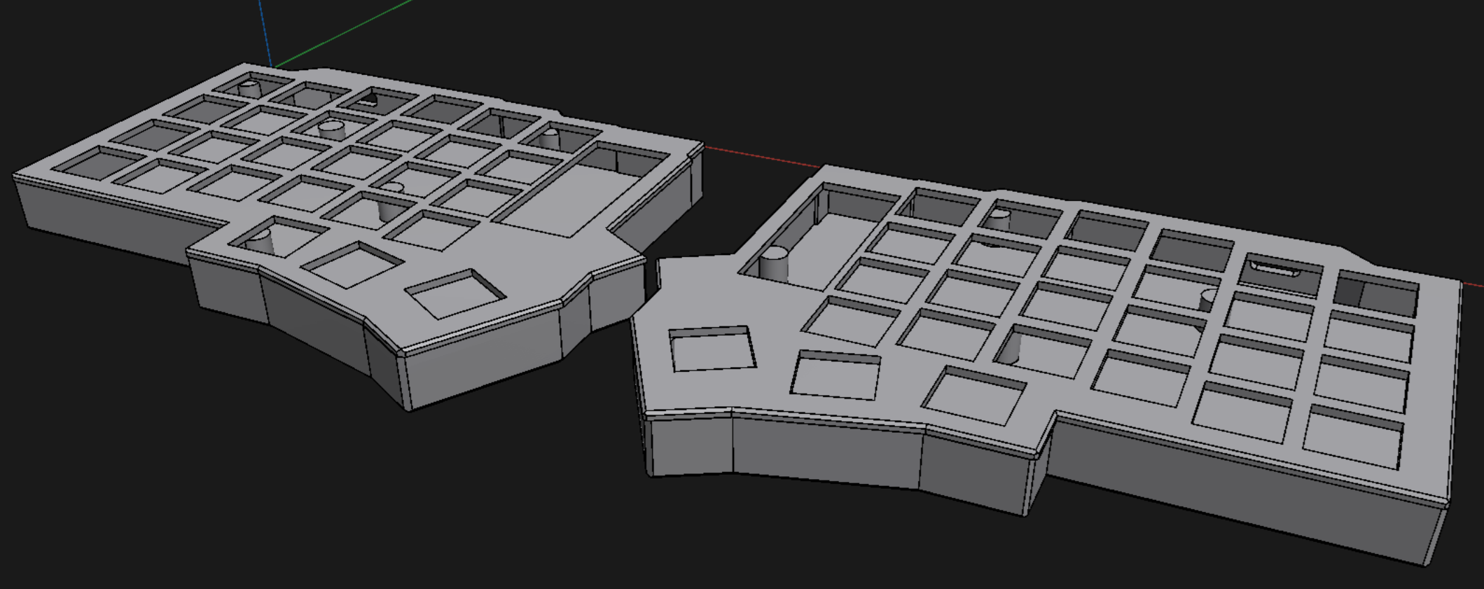
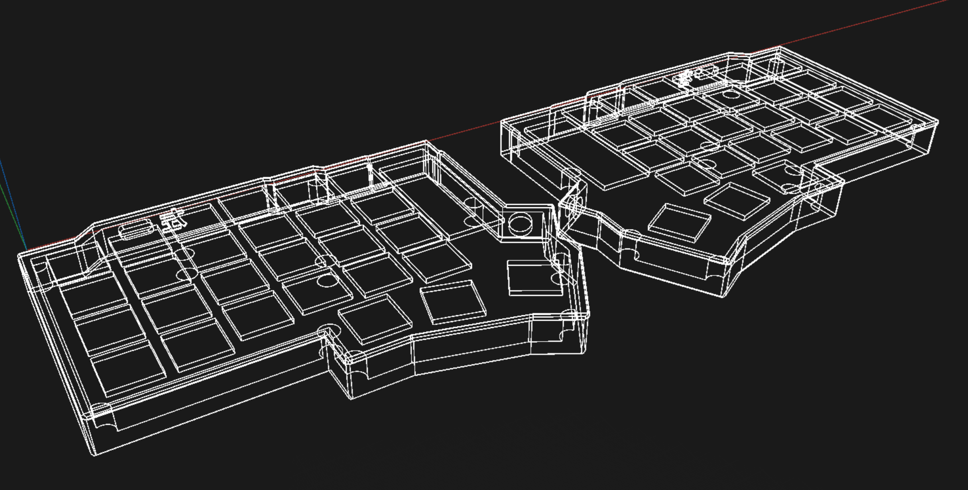
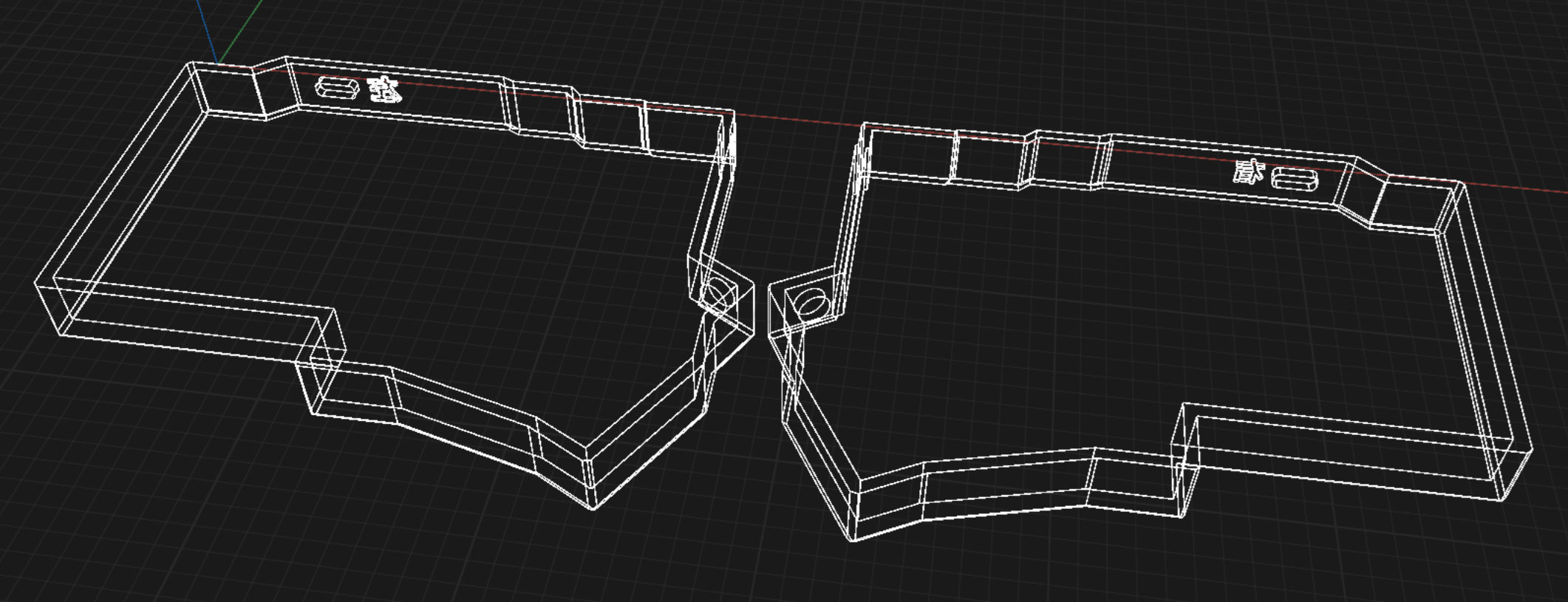
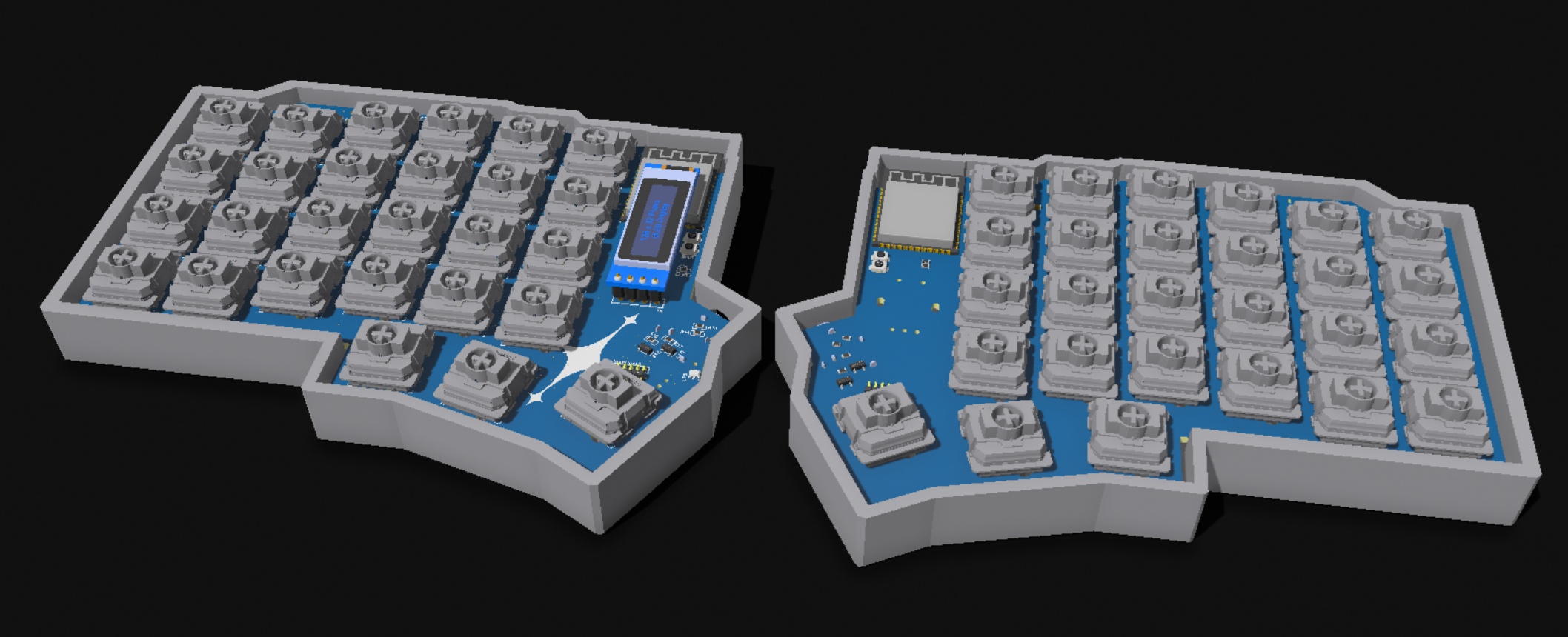
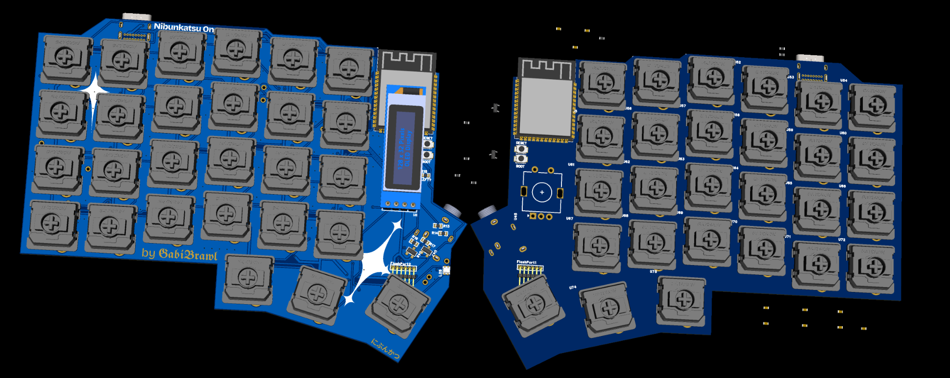
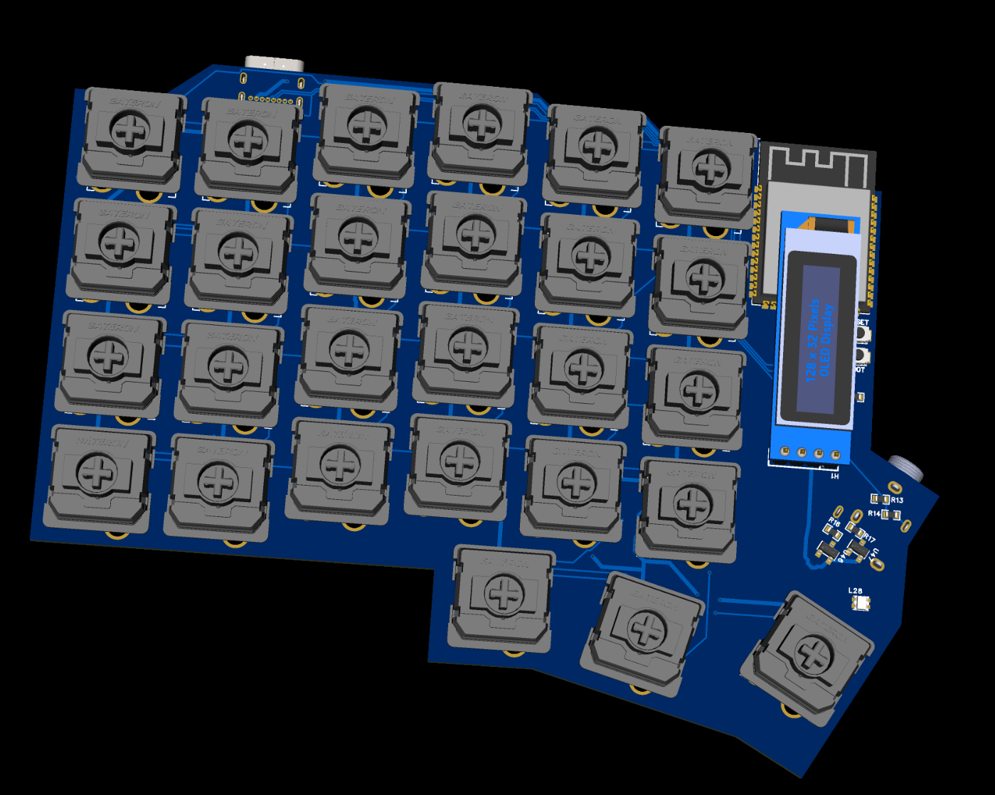
11/12/2025 - 3D Model Improvements
After procrastinating for a while, I finally decided to improve on the 3D models more. Added support cylinders to hold the PCBs in the right height, and made the plates where the switches will be mounted on! Now there are 4 models to be printed: Left case, Right case, Left plate and Right plate.
GabiBrawl
added to the journal ago
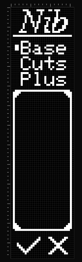
10/12/2025 - Oled display UI design
Made a sample UI design that fits the vertical layout of the 0.91 inch display, and tested it on an actual display module. I looked up online and didn't find anyone using this display in vertical orientation, so I had to improvise a bit. But it is turning out great! This is by no means the final, but gives a taste. :P Everything was designed using lopaka.app, which is an amazing tool for making pixel art and small UIs for displays like this.
GabiBrawl
added to the journal ago
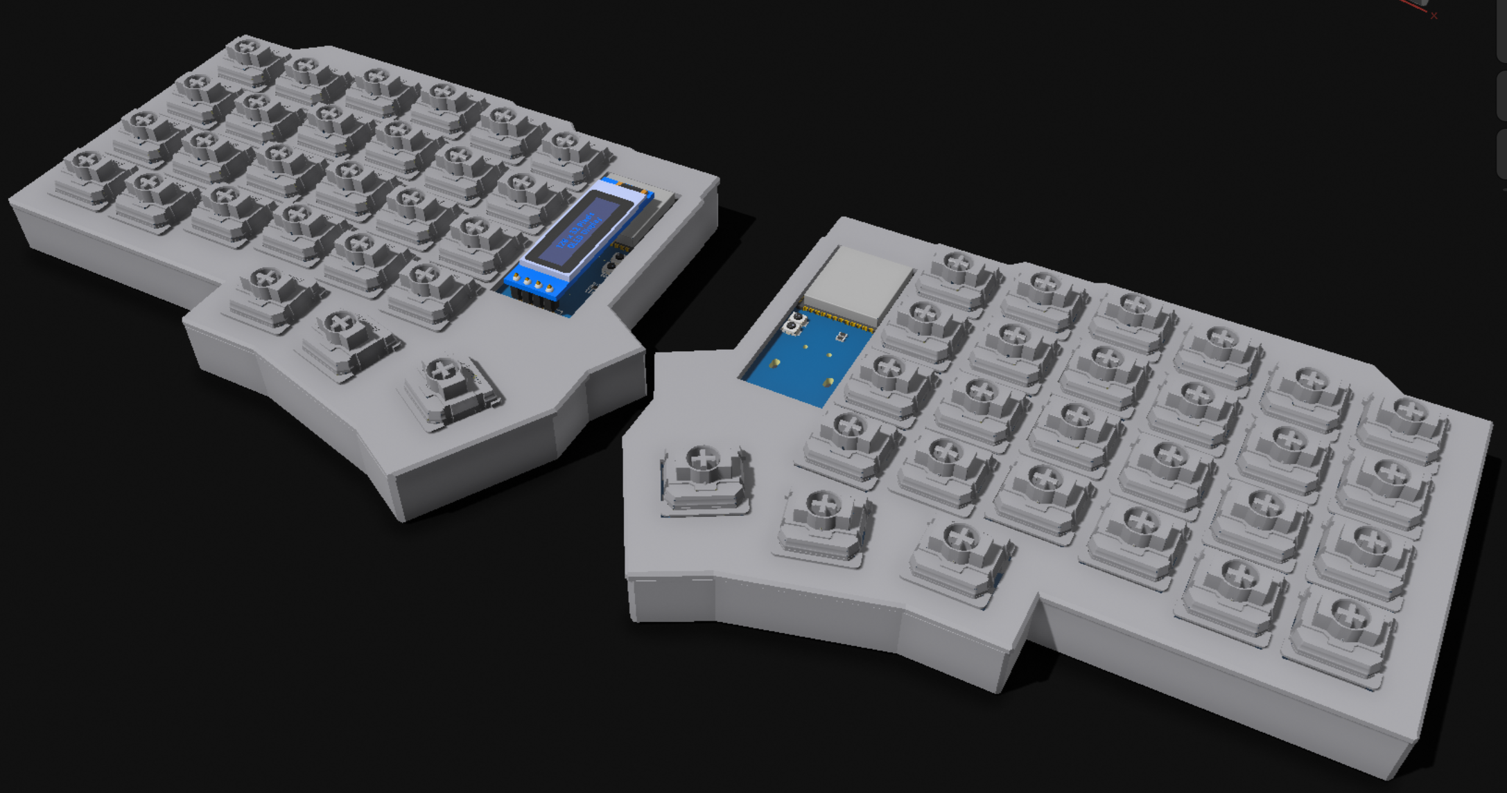
08/12/2025 - 3D CAD Modeling
Following Joe Scotto's tutorial on youtube, I made the 3D case model for both sides of Nibunkatsu using Shapr3D! This is my first time modeling something in 3D, and I'm absolutely impressed by the result!! This is so much easier than I've ever expected it to be :D
GabiBrawl
added to the journal ago
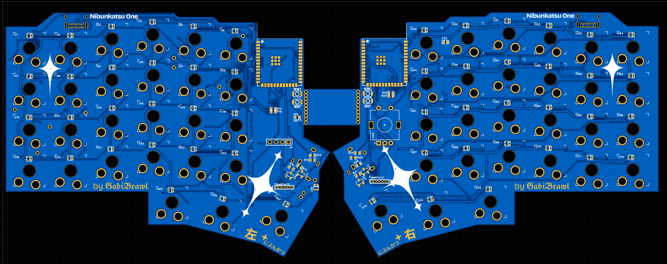
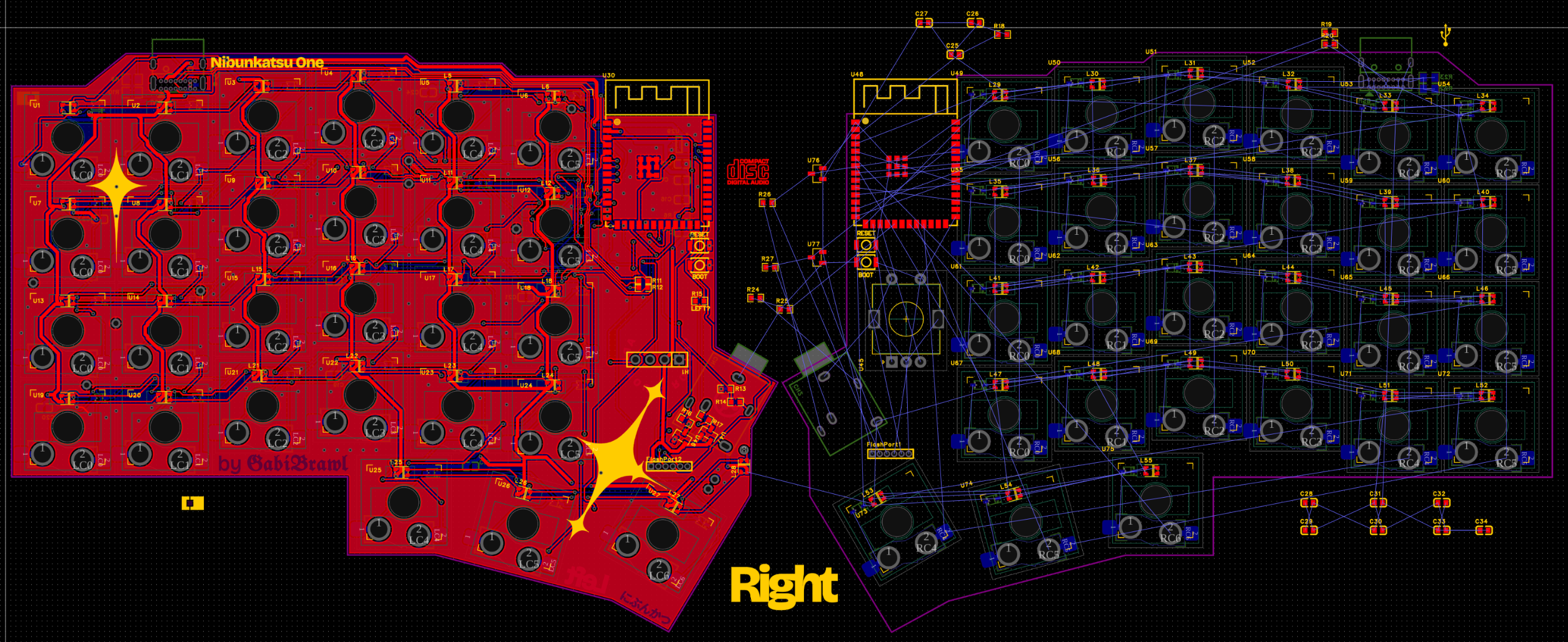
06/12/2025 - Final PCB design
Fixed various schematic errors some I spotted by myself, and others with the help of Gemini too. With these fixes routing the PCBs was finalized as well.

GabiBrawl
added to the journal ago
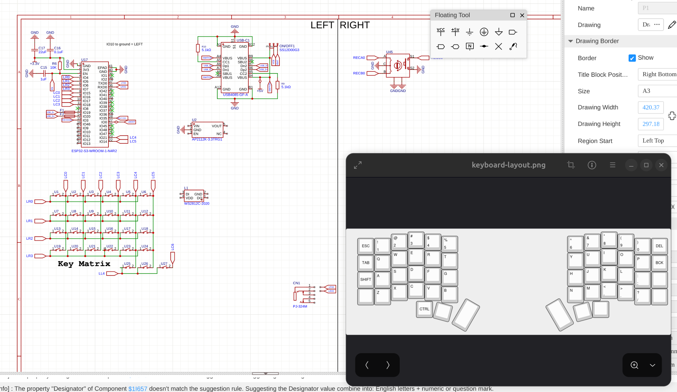
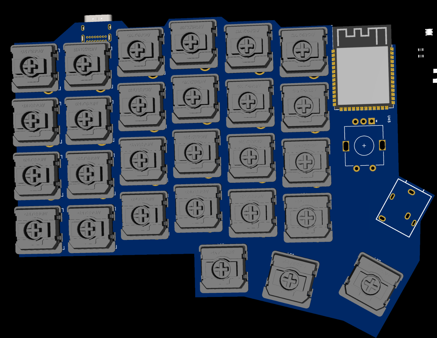
05/12/2025 - Even more planning and design
After getting the left keyboard side mostly wired up, I began the right side by cloning the left side outline and flipping it, like this I ensured that both sides are as similar as I can possibly get them.
Also I made custom artwork stars in Figma and added them into the PCBs. I went for some sort of a cybersigilism look, which I love <3
GabiBrawl
added to the journal ago
04/12/2025 - More planning and design
Today focused on refining the PCB design and schematics, primarily for the left half of the keyboard. A major part of the work involved researching protection mechanisms for the TRRS connection—specifically, how to prevent 5V shorts to the UART pins during hot-plugging, which is critical for protecting the MCU from high-voltage damage.
GabiBrawl
added to the journal ago
03/12/2025 - Research, Planning and Design
I kicked off the project by deep-diving into split keyboard videos to fully grasp the mechanics and standard build processes.
From there, I moved on to designing the layout and picking components. I started the schematics and PCB for the left side today—already factoring in the rotary encoder for the right half—and spent quite a while manually placing every single switch to get the spacing just right.
Iamalive 🚀
requested changes for Nibunkatsu One, a Split Keyboard ago
This should be marked as following the split keyboard guide. Currently its listed as a hackpad. Please fix this!
GabiBrawl
submitted Nibunkatsu One, a Split Keyboard for ship review ago
GabiBrawl
started Nibunkatsu One, a Split Keyboard ago
12/11/2025 3:20 PM - 03/12/2025 - Research, Planning and Design
I kicked off the project by deep-diving into split keyboard videos to fully grasp the mechanics and standard build processes.
From there, I moved on to designing the layout and picking components. I started the schematics and PCB for the left side today—already factoring in the rotary encoder for the right half—and spent quite a while manually placing every single switch to get the spacing just right.
12/11/2025 3:30 PM - 04/12/2025 - More planning and design
Today focused on refining the PCB design and schematics, primarily for the left half of the keyboard. A major part of the work involved researching protection mechanisms for the TRRS connection—specifically, how to prevent 5V shorts to the UART pins during hot-plugging, which is critical for protecting the MCU from high-voltage damage.
12/11/2025 3:40 PM - 05/12/2025 - Even more planning and design
After getting the left keyboard side mostly wired up, I began the right side by cloning the left side outline and flipping it, like this I ensured that both sides are as similar as I can possibly get them.
Also I made custom artwork stars in Figma and added them into the PCBs. I went for some sort of a cybersigilism look, which I love <3
12/11/2025 3:46 PM - 06/12/2025 - Final PCB design
Fixed various schematic errors some I spotted by myself, and others with the help of Gemini too. With these fixes routing the PCBs was finalized as well.
12/11/2025 3:49 PM - 08/12/2025 - 3D CAD Modeling
Following Joe Scotto's tutorial on youtube, I made the 3D case model for both sides of Nibunkatsu using Shapr3D! This is my first time modeling something in 3D, and I'm absolutely impressed by the result!! This is so much easier than I've ever expected it to be :D
12/11/2025 3:53 PM - 10/12/2025 - Oled display UI design
Made a sample UI design that fits the vertical layout of the 0.91 inch display, and tested it on an actual display module. I looked up online and didn't find anyone using this display in vertical orientation, so I had to improvise a bit. But it is turning out great! This is by no means the final, but gives a taste. :P Everything was designed using lopaka.app, which is an amazing tool for making pixel art and small UIs for displays like this.
12/11/2025 3:56 PM - 11/12/2025 - 3D Model Improvements
After procrastinating for a while, I finally decided to improve on the 3D models more. Added support cylinders to hold the PCBs in the right height, and made the plates where the switches will be mounted on! Now there are 4 models to be printed: Left case, Right case, Left plate and Right plate.
12/13/2025 - 13/12/25 - Repository organization and fixes
Fixed plenty of things in the repository, and made changes to the BOM and License choice reasoning.
This post will also serve as a fix for the project banner, as I've discovered why it kept being white in spite of all images I added! This is the hero image I used for the github repository of the project.
1/2/2026 8:02 PM - 01/01/26 - Soldering and coding...
Before anything, Happy new year! :D
The PCB arrived and most components too! I soldered the minimal components to get the ESP32 chip working through the USB port so I could start developing some code. Little did I know that getting the ESP32-S3 N4 would bring nothing but issues... (if you're getting an N4, get at least the N4R2)
My initial plans for the project was to use Circuit Python and KMK, but no builds are available for the N4 apparently. I tried developing in Platformio something then, and oh boy I couldn't get the ESP to boot normally without bootlooping. I spent the whole day troubleshooting and making a semi-custom compiler in Platformio for this chip... (yes Grok Code Fast 1 did most of the heavy lifting here, but I had to research some old solutions that worked in the past but no longer now too)
For now I started development using the Arduino Framework but I will try to move into ESP-IDF instead.
I got the RGB working and some kind of key scanning and basic hid input working.
1/2/2026 8:22 PM - 02/01/26 - More soldering, testing and discovery!
The Aliexpress parts arrived today!
I spent some time developing the firmware, soldering the LEDs, the 3.5mm connector, and the hotswap sockets. As with any prototype, a few challenges appeared:
- The first LED in the matrix is currently acting only as a signal amplifier. To stabilize the data for the rest of the chain, I had to keep it turned off. This is a functional workaround for now. For the future I'll add an LED spot only for signal amplification, outside of the matrix.
- I realized I accidentally used a TRS (3-pin) connector instead of a TRRS (4-pin). Since I’m short on pins for wired data, I’ve pivoted: the 3.5mm cable will now only provide power to the secondary half, and I’ll use ESP-NOW for wireless communication between the two sides.
- The switch spacing is a bit too tight, which means my standard keycap set won't fit. My immediate solution is to 3D print custom, more compact keycaps for this specific revision.
Errors are how you learn. I’ve applied lessons from past failures to fix old bugs, even if new ones took their place. I’m still aiming for a "perfectly baked" Nibunkatsu keyboard, so for now, I’ll bridge these gaps to get it functional and prepare for the next board revision!
1/19/2026 - 03/01/26 - More coding
Today was dedicated more to some coding refinements and better sync both halves of the keyboard wirelessly via ESP-IDF. Also created a debug menu with info from both sides. the menu shows up when holding IO0 to GND.
I chose the wrong 3.5mm connector. I thought the connector had 5 pins cuz it had 4 contact points and a detection pin, but no. It has 3 pins and 2 detection pins for some reason. So the original plan for both halves to communicate together via the TRRS cable with the TX and RX pins was scrapped in favor of ESP-IDF communication. The 3.5mm connector only powers the right half with 5V and GND.
Multiple optimizations have been made to key scanning, RGB handling and some other things.
1/30/2026 - 09/01/26 - Received Final Parts & Finished the Assembly!
The final boxes from AliExpress arrived, so the assembly was concluded on this day!
The process was pretty straight forward:
- open the 100 plastic packets from aliexpress
- sort the components
- soldered the LEDs, then the hotswap sockets and finally the rotary encoder
- then slotted the boards on the 3D prints and manually fixed some minor fitting issues
- plugged everything in, made multiple firmware adjustments and got a functional keyboard!!
More assembly details
- The first LED in each board hat to be shut off completely. This is due to it being used to boost the signal from 3v3 to 5v. The ESP can only send 3V3 signals through it's GPIO, so the first led is the only one being powered from the 3V3 rail, and all the rest are on the 5V rail. The LEDs in the 3V3 rail can take a 3V3 signal, but the 5V leds require a 5V signal. So to overcome this, we use the first LED to step up the signal voltage, but had to turn it off via firmware so that it doesn't get into power drops when changing color to brighter tones.
- I had to pivot from TRS to ESP-NOW, after realizing that the 3.5mm connector jack was only a 3-pin (TRS) and not a 4-pin (TRRS) as expected so I had to re-code the firmware to use ESP-NOW for wireless communication between the halves. The physical cable is only used for 5V power transmission now.
FINALIZED PICS:
Issues I faced:
I placed the keys too close together, and the keycaps set I ordered doesn't fit >:
I have two fixes for this: for the short term I'll print custom keycaps and use those. For the longer term I'll make new PCBs fixing all issues I faced and order them whenever I have money xD
A whole column of keys on each side doesn't register clicks. I will have to rewire it manually.