Ryan's Cognitive Smart Ring
This is a sensor packed device that features a GSR sensor and max30102 sensor that measure skin electrical conductivity (arousal), temperature, spo2, heart rate, HRV, and an accelerometer for filtering. The point of this is to build a tracker that isn't focused on fitness, but cognitive health tied to the nervous system. These sensors will be packed into a small flex PCB in a ring shape.. All of the circuitry has been tested in LT-Spice to ensure electrical correctness. The key point of this project is to have this ring focused on mental and cognitive health rather than fitness and physical health. So, the sensors send data to the Raytac nRF52840 module and the Raytac sends it to a mobile device via BLE. The data goes through a filter in the app, removing any outliers. Additionally, in the app there is a "Cognitive Score." The app interprets all the data and based off of an algorithm, it can give you a score out of 100 as well as some insights.
Created by
 NRG
NRG
Tier 1
14 views
0 followers
NRG
added to the journal ago
3D Print Time
So I need to design a case that is perfect for my finger being mindful of the 1.55mm thick battery, flex pcb, stiffeners, and the subtracted radius from the way the stiffeners bend. It is modeled here and I also need to create a holding place for the battery to keep it even.

NRG
added to the journal ago
Simulated the Rigid-Flex
In CAD and real life, I used paper to represent the flex polymide and cardboard as FPC stiffeners. I arranged the stiffeners in a way that it the flex could bend into a ring circle.


NRG
added to the journal ago
Good news for the reviewers!! This project actually works
You dont have to be worried that this project is a waste of your money. I created a new PCB that just has the sensors. If you scroll down its labeled as version 2. So I ordered it with my own money just because I was neurotic, and everything works. So I'm 99% sure that my new Version 3, which the grant money is for, will work. Just to clear things up because this sounds confusing. The version 2 test board was ordered with my own money. The grant is for version 3, which is the full flex PCB including the MCU. Here are some pictures of it actually working.


NRG
submitted Ryan's Cognitive Smart Ring for review ago
NRG
added to the journal ago
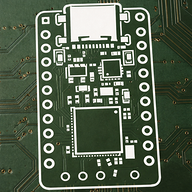
Flex PCB - Part Two
Okay I made some edits and completely removed the charging block because it takes up way too much space and I can easily charge the battery externally. I measured out the length and width that I should use for the layout and properly layed everything out. All of the decoupling caps are where they should be and the distance between the sensor and mcu is appropraite. I used a hatched ground fill so it doesn't interfere with the flex. 
NRG
added to the journal ago
Version 3: Flex PCB Part 1
I copied and pasted my version 2 sensor board schematic into my new project. For the logic board, I will be using the Raytac MDBT50Q which is a nrf52840 board with a built in LDO and crystal. Next, I had to figure out how to do the charging and data usb system. First I added the port, then the MCP charger. Later, I added an ESD array for protection.In order to power the MCU with both the 5V USB system and the 3.7 volt LiPo, I created a 2 Schottky diode OR-ing system. This system allows the 5v usb power to take priority and power the VDDH pin when it is present. Otherwise, the 3.7 lipo powers the VDDH. The VDD pin is the LDO output for the sensors and what the nrf actually runs on. Also, there is a DC-DC mode I may use with the inductor.


 Jay ⚡🚀
requested changes for Ryan's Cognitive Smart Ring ago
Jay ⚡🚀
requested changes for Ryan's Cognitive Smart Ring ago
as you requested!
NRG
added to the journal ago
Version 2
Alright so in these 3 weeks, I made a completely new version that costs a bit less and is more efficient. Essentially the difference is that I would use a XIAO nrf52840 breakout board instead of my custom logic board. Then, I would have my compact, HIGHLY reviewed and refined sensor board with a new LDO, operational amplifier, and accelerometer. This would be PCBA by JLCPCB simply because its cheaper to have them assemble it than buy the rework station for assembly at home.
This new system is simple, small, and functional but it is not designed optimally. I would like to decrease thickness and make it a lot sleeker.
This sets us up for our final version: v3. I am going to use this new refined sensor board schematic, but I will integrate my own logic board on a flex PCB.
New Everything:


NRG
added to the journal ago
Touched up the PCB
I fixed some of the ratlines BUT there are still some ratlines because there is an interconnect so just don't pay attention to those.
Also I fixed the GND plate..rerouted the whole thing better. 
NRG
submitted Ryan's Cognitive Smart Ring for review ago
NRG
added to the journal ago
Completely changed the PCB

Okay so the one big PCB was a scary and probably a big design flaw because it would be uncomfotable for the user to wear. Instead, I split the PCB into two main boards, one for each finger. Board A is the logic board with the MCU and whatnot. Board B is the sensor board. On the edges of each board are the interconnect pads with 5 pins each including VDD, GND, I2C pins.
 Kai the Jolly Guy 🚀
requested changes for Ryan's Cognitive Smart Ring ago
Kai the Jolly Guy 🚀
requested changes for Ryan's Cognitive Smart Ring ago
Hey there, I like the idea but you have ratlines on your PCB that need to be fixed, and your project complexity doesn't justify $320. Please get your project under at least $100 before we take a second look, and significantly optimize your BOM. I also don't understand how you're going to connect everything together, and power this thing because I don't see a battery or anything along those lines? Ask in #blueprint for help with optimizing your project!
NRG
submitted Ryan's Cognitive Smart Ring for review ago
 Iamalive 🚀
requested changes for Ryan's Cognitive Smart Ring ago
Iamalive 🚀
requested changes for Ryan's Cognitive Smart Ring ago
Your cart screenshots add up to $274.8s, which differs from your requested funding. Please fix this discrepancy and resubmit.
NRG
added to the journal ago
Touched up the PCB and rerouted some wires.
I rerouted some wires on my PCB just for more organization and improved the via layouts. A lot of my BCU tracks are on the horizontal axis while my FCU tracks are going up and down vertical axis.

NRG
submitted Ryan's Cognitive Smart Ring for review ago
 PenguinMo
requested changes for Ryan's Cognitive Smart Ring ago
PenguinMo
requested changes for Ryan's Cognitive Smart Ring ago
The price is still the same, try using temu for the Amazon parts
NRG
submitted Ryan's Cognitive Smart Ring for review ago
PenguinMo
requested changes for Ryan's Cognitive Smart Ring ago
Try to reduce cost some part on your checkout list are on amazon and are cheaper on temu or aliexpress
NRG
submitted Ryan's Cognitive Smart Ring for review ago
NRG
added to the journal ago
Added pictures of PCB
I updated my readme to include direct images of my PCB and the 3D image of my PCB. For any more PCB details, there is a folder in my github repo that says Ring PCB and Schematic. There are more pictures including the schematic and the direct files of everything including gerber.

Jay ⚡🚀
requested changes for Ryan's Cognitive Smart Ring ago
your readme mentions a PCB and you also add that to you read me like pictures of it?
NRG
submitted Ryan's Cognitive Smart Ring for review ago
Jay ⚡🚀
requested changes for Ryan's Cognitive Smart Ring ago
i still dont see a BoM.csv file
NRG
submitted Ryan's Cognitive Smart Ring for review ago
NRG
added to the journal ago
Find the cheapest possible options and make the BOM.csv
I had a google spreadsheet, but I am downloading it into a CSV. Also I reduced the price by almost 30 dollars and found the ABSOLUTE best price including shipping. I tried to use some Aliexpress parts but they didn't have the exact thing I needed.
Iamalive 🚀
requested changes for Ryan's Cognitive Smart Ring ago
Please add a BOM.csv to your project, and also try to find some cheaper parts from other retailers instead of buying from Amazon! (Think aliexpres, temu, etc)
NRG
submitted Ryan's Cognitive Smart Ring for review ago
NRG
added to the journal ago
I am making a more comprehensive CAD in Fusion 360.
I downloaded fusion 360, got the hang of it, then I imported my PCB stl file from KiCad and designed the 2 rings, embedded the pcb, added the battery, cut holes, hid the pcb away, and added the electrodes and a connecting wire. See the hole thing in Git Repo


 Tanuki ⚡🚀
requested changes for Ryan's Cognitive Smart Ring ago
Tanuki ⚡🚀
requested changes for Ryan's Cognitive Smart Ring ago
THis is cool, however, I dont see the CAD in the journal. THe journal should show the full building process, with more depth (not just the final product, but the actual steps whilst building it.) Also, the CAD should be more complex. I would recc Onshape or fusion. Looking nice!
NRG
submitted Ryan's Cognitive Smart Ring for review ago
NRG
added to the journal ago
Routed the PCB
I routed the SUPER tight PCB and used both top and bottom layers. I adjusted some pins in the schematic so I could get all the pins corrected with no interference or DRC errors.
I got this done in three long sessions:
OHH also I learned all about vias and track widths because I ran into an issue where the inner pins of the MCU were not able to be routed out, so what I did was reduced width requirements, then I made a smaller track, placed a via, and was able to get through that wall. Its screenshot is below


NRG
added to the journal ago
Layed out the PCB and got rid of Schottky diode.
I learned how layers worked, how to use KiCad PCB editor. I somehow layed out the PCB very tightly with no DRC errors. All of the capacitors are nearby their pins and resistors are in proper place. In this session, I updated my PCB from my schematic and also cut out the D_Schottky Diode. Here is my process in screenshots: 


NRG
added to the journal ago
Set up the schematic/researched parts.
Learned everything about schematics, parts, pins, pads, nets, etc. Built a schematic for the PCB including the max30102 and the gsr sensor. I also fiddled with different LDOs and battery protectors.
I started out with a double NMOS but then decided to proceed without them.
I watched a lot of youtube videos on a guide through kiCad
Below, you can see my progress and process:


NRG
added to the journal ago
Figure out XCode
I had to learn how to use VSCODE and XCODE together and made some tweaks to my iPhone to get the app running and installed. Also had to figure out BLE permissions. Also learned how to send data BLE with some random BLE apps.
NRG
added to the journal ago
Built Arduino IDE code for MCU nrf52840
Built code for MCU nrf. This code sends the data connected from SCL, SDA, and analog 0 pins and transmits it over BLE with several different UUIDs. I looked at online guides to the max30102 sensor and also the gsr sensor, combined it, and learned how to use the Arduino BLE library. My last update to the code was 2 weeks ago. Again, I started this before but I have many variations to this code I will show: The code is linked in GitHub. 

NRG
added to the journal ago
Created iOS flutter app for device.
First I created the flutter app running on XCODE iOS. It is linked in the GitHub repository. Small tweaks in the algorithm and filtering have been done. I know you want to see the process but I started this during the fall and I don't have anything to show for progress but I am constantly making UI tweaks, and new features. Last week I added the temperature feature that is on the max30102 to the UI. 

 1Mon ⚡
requested changes for Ryan's Cognitive Smart Ring ago
1Mon ⚡
requested changes for Ryan's Cognitive Smart Ring ago
please journal your process of creating this project!
NRG
submitted Ryan's Cognitive Smart Ring for review ago
 zsharpminor
requested changes for Ryan's Cognitive Smart Ring ago
zsharpminor
requested changes for Ryan's Cognitive Smart Ring ago
This looks great conceptually BUT you sadly need a complete PCB, CAD, and code as well as a README filled with images and a BOM before you can be accepted, especially for a Tier 1 project! You can do it, though!
NRG
submitted Ryan's Cognitive Smart Ring for review ago
NRG
started Ryan's Cognitive Smart Ring ago
12/12/2025 12 PM - Created iOS flutter app for device.
First I created the flutter app running on XCODE iOS. It is linked in the GitHub repository. Small tweaks in the algorithm and filtering have been done. I know you want to see the process but I started this during the fall and I don't have anything to show for progress but I am constantly making UI tweaks, and new features. Last week I added the temperature feature that is on the max30102 to the UI.
12/12/2025 1:05 PM - Built Arduino IDE code for MCU nrf52840
Built code for MCU nrf. This code sends the data connected from SCL, SDA, and analog 0 pins and transmits it over BLE with several different UUIDs. I looked at online guides to the max30102 sensor and also the gsr sensor, combined it, and learned how to use the Arduino BLE library. My last update to the code was 2 weeks ago. Again, I started this before but I have many variations to this code I will show: The code is linked in GitHub.
12/12/2025 1:09 PM - Figure out XCode
I had to learn how to use VSCODE and XCODE together and made some tweaks to my iPhone to get the app running and installed. Also had to figure out BLE permissions. Also learned how to send data BLE with some random BLE apps.
12/12/2025 1:11 PM - Set up the schematic/researched parts.
Learned everything about schematics, parts, pins, pads, nets, etc. Built a schematic for the PCB including the max30102 and the gsr sensor. I also fiddled with different LDOs and battery protectors.
I started out with a double NMOS but then decided to proceed without them.
I watched a lot of youtube videos on a guide through kiCad
Below, you can see my progress and process:
12/12/2025 1:14 PM - Layed out the PCB and got rid of Schottky diode.
I learned how layers worked, how to use KiCad PCB editor. I somehow layed out the PCB very tightly with no DRC errors. All of the capacitors are nearby their pins and resistors are in proper place. In this session, I updated my PCB from my schematic and also cut out the D_Schottky Diode. Here is my process in screenshots:
12/12/2025 1:16 PM - Routed the PCB
I routed the SUPER tight PCB and used both top and bottom layers. I adjusted some pins in the schematic so I could get all the pins corrected with no interference or DRC errors.
I got this done in three long sessions:
OHH also I learned all about vias and track widths because I ran into an issue where the inner pins of the MCU were not able to be routed out, so what I did was reduced width requirements, then I made a smaller track, placed a via, and was able to get through that wall. Its screenshot is below
12/12/2025 11 PM - I am making a more comprehensive CAD in Fusion 360.
I downloaded fusion 360, got the hang of it, then I imported my PCB stl file from KiCad and designed the 2 rings, embedded the pcb, added the battery, cut holes, hid the pcb away, and added the electrodes and a connecting wire. See the hole thing in Git Repo
12/13/2025 9 AM - Find the cheapest possible options and make the BOM.csv
I had a google spreadsheet, but I am downloading it into a CSV. Also I reduced the price by almost 30 dollars and found the ABSOLUTE best price including shipping. I tried to use some Aliexpress parts but they didn't have the exact thing I needed.
12/13/2025 11 AM - Added pictures of PCB
I updated my readme to include direct images of my PCB and the 3D image of my PCB. For any more PCB details, there is a folder in my github repo that says Ring PCB and Schematic. There are more pictures including the schematic and the direct files of everything including gerber.
12/17/2025 - Touched up the PCB and rerouted some wires.
I rerouted some wires on my PCB just for more organization and improved the via layouts. A lot of my BCU tracks are on the horizontal axis while my FCU tracks are going up and down vertical axis.
1/5/2026 - Completely changed the PCB
Okay so the one big PCB was a scary and probably a big design flaw because it would be uncomfotable for the user to wear. Instead, I split the PCB into two main boards, one for each finger. Board A is the logic board with the MCU and whatnot. Board B is the sensor board. On the edges of each board are the interconnect pads with 5 pins each including VDD, GND, I2C pins.
1/6/2026 - Touched up the PCB
I fixed some of the ratlines BUT there are still some ratlines because there is an interconnect so just don't pay attention to those.
Also I fixed the GND plate..rerouted the whole thing better.
1/18/2026 - Version 2
Alright so in these 3 weeks, I made a completely new version that costs a bit less and is more efficient. Essentially the difference is that I would use a XIAO nrf52840 breakout board instead of my custom logic board. Then, I would have my compact, HIGHLY reviewed and refined sensor board with a new LDO, operational amplifier, and accelerometer. This would be PCBA by JLCPCB simply because its cheaper to have them assemble it than buy the rework station for assembly at home.
This new system is simple, small, and functional but it is not designed optimally. I would like to decrease thickness and make it a lot sleeker.
This sets us up for our final version: v3. I am going to use this new refined sensor board schematic, but I will integrate my own logic board on a flex PCB.
New Everything:
1/23/2026 - Version 3: Flex PCB Part 1
I copied and pasted my version 2 sensor board schematic into my new project. For the logic board, I will be using the Raytac MDBT50Q which is a nrf52840 board with a built in LDO and crystal. Next, I had to figure out how to do the charging and data usb system. First I added the port, then the MCP charger. Later, I added an ESD array for protection.In order to power the MCU with both the 5V USB system and the 3.7 volt LiPo, I created a 2 Schottky diode OR-ing system. This system allows the 5v usb power to take priority and power the VDDH pin when it is present. Otherwise, the 3.7 lipo powers the VDDH. The VDD pin is the LDO output for the sensors and what the nrf actually runs on. Also, there is a DC-DC mode I may use with the inductor.
1/24/2026 - Flex PCB - Part Two
Okay I made some edits and completely removed the charging block because it takes up way too much space and I can easily charge the battery externally. I measured out the length and width that I should use for the layout and properly layed everything out. All of the decoupling caps are where they should be and the distance between the sensor and mcu is appropraite. I used a hatched ground fill so it doesn't interfere with the flex.
2/2/2026 - Good news for the reviewers!! This project actually works
You dont have to be worried that this project is a waste of your money. I created a new PCB that just has the sensors. If you scroll down its labeled as version 2. So I ordered it with my own money just because I was neurotic, and everything works. So I'm 99% sure that my new Version 3, which the grant money is for, will work. Just to clear things up because this sounds confusing. The version 2 test board was ordered with my own money. The grant is for version 3, which is the full flex PCB including the MCU. Here are some pictures of it actually working.
2/7/2026 7:54 PM - Simulated the Rigid-Flex
In CAD and real life, I used paper to represent the flex polymide and cardboard as FPC stiffeners. I arranged the stiffeners in a way that it the flex could bend into a ring circle.
2/7/2026 7:58 PM - 3D Print Time
So I need to design a case that is perfect for my finger being mindful of the 1.55mm thick battery, flex pcb, stiffeners, and the subtracted radius from the way the stiffeners bend. It is modeled here and I also need to create a holding place for the battery to keep it even.