IRIS (Integrated Rocket Intelligence System)
A quite advanced flight computer, designed for my guided rocket. Also coincidentally my first hardware project. Uh oh.
Created by
 tty7 ⚡
Tier 1
40 views
1 follower
 Iamalive 🚀
approved IRIS (Integrated Rocket Intelligence System) ago
Iamalive 🚀
approved IRIS (Integrated Rocket Intelligence System) ago
Tier approved: 1
Grant approved: $253.00
Honestly AWESOME project! I'll approve thing on one condition - please organize your bom a little bit, as how it stands right now it's a bit confusing how the funding would be used (totally not because it took me 10 minutes to figure it out sob)
tty7 ⚡
added to the journal ago
fix banner image (DUMMY ENTRY)
fix the banner image since it doesn't let you set that for some stupid reason. Please ignore this time and this journal entry, nothing was done (I'm not submitting for build review anyway and I set it as low as I could put it), this is literally just so I can have a banner image that doesn't look like trash

tty7 ⚡
added to the journal ago
Added some silkscreen art + credits
I finally got around to doing what I had been meaning to from the start and adding some silkscreen art and credits. I especially want to thank @mpk for helping me through every step of the radio frequency design, and for supporting me through the process. If anybody deserves a place on the board, it's him. I'd also like to thank Kai Pereira for giving me some really good tips on how to improve my board, and for everybody on the blueprint team for answering my questions.
Thanks to everybody that helped me in any way along this process, it was quite the journey.

(no I'm not redoing my blender renders that was painful enough and it's close enough)
tty7 ⚡
added to the journal ago
Changed the flash chip
I was doing some math and checking over everything, and realized that the flash chip I had chosen was probably a little bit too small. It was 4 cents more per component (so 8 cents total) to get double the storage from the exact same model series as what I was using, so I changed the component.
Since it didn't let me when I submitted, this is for a project banner image (rather crappy but oh well):

I really hope that works
For reviewers, here's the cart screenshots of the parts that changed:


tty7 ⚡
submitted IRIS (Integrated Rocket Intelligence System) for ship review ago
tty7 ⚡
added to the journal ago
Final pass through the BoM
I went through the bom and tried to get the parts sourced from the cheapest source I could, and also MODIFIED IT FOR 2 BOARDS SINCE HACK CLUB IS AMAZING!!!!!
Thanks a lot to the review team for being patient with me while I tried to explain my design decisions as best as I could, and for letting me buy parts for 2.
New bom with everything added up:

LCSC saved me like $20 on the 2 gps's alone, it was crazy how much it saved (cut ~$40 off of the bom!)
tty7 ⚡
added to the journal ago
Minor finishing touches
I did some super minor finishing touches, like fixing the trace impedance on my vr_pa trace (thanks to mpk again for helping me figure out the impact of the vias on the trace's impedance) and adding the rendered picture to my readme. I did have to keep exporting and rerendering that picture because the colors didn't look right with the color management settings I had been picking (thanks a lot, Blender), but oh well.
Here's the (probably) final readme:

tty7 ⚡
added to the journal ago
Fought with Blender to get a render
I thought getting a render of my board wouldn't be that hard. I was wrong.
The first problem was that I was missing some 3d models of my components. Oh well, I just found some and added it. No problem!
Then I had to export the board. Very easy with pcb2blender. This is going great so far!
Then began the real work. It was SO HARD to get the board lit the way I wanted, and I ended up with way more lights than I thought I needed, then eventually replaced a bunch of them with area lights. Alright, it's lit, we're good, right?
NO! The exported board had the wrong materials for a bunch of stuff, and I had to figure out what texture everything was, was it metal or not, should it have scratches, so on and so forth.
After I got the textures fixed, you'd think I'd be done, right? Again, NO! For some stupid reason in my little pea sized brain, I decided I wanted an animation despite having forgotten how to use blender entirely. Needless to say, that was a REALLY STUPID IDEA. I spent way too long trying to get the camera paths looking good, and I know how I could do it way better now, but I really don't want to have to rerender it (8 hours of my rtx 3080 going crazy). It's good enough for me.
I got a pretty decent (in my opinion) render of the board:

And an "ok" (actually really bad now that I know how to do it better but oh well) animation which includes a rough model of the rocket it's going in:
animated render
Obviously the time for this journal does not include render time, I just suck that much at blender.
tty7 ⚡
added to the journal ago
Wrote a README! Still need pictures
I put a lot of effort into my readme, especially the design reasoning section. There are a lot of expensive components that I'm using, that would make nearly zero sense for somebody just following the tutorial. That tutorial didn't exist when I started this project, and I actually have a flight vehicle being designed for this computer. It's actually going to fly on a guided rocket, which means the requirements for it are MUCH higher than a basic flight computer. Unfortunately, unless I explain that, the reviewers won't know why I picked what I did and my project will get rejected.
The only thing I have left to do in the readme is getting a render, which surely won't be too hard, right? (future me: IT SUCKED SO MUCH AND THAT WAS NOT GOOD)
Here's the readme:

tty7 ⚡
added to the journal ago
Fixed micro sd part 3, came up with a name
Turns out I never really got the hand of the micro sd card, I used the flight computer tutorial as a reference to see which pullups I was missing (based off of some of the research I had done, it seemed pretty likely I was missing some).
I was missing a lot.
It wasn't very hard to add, just a pretty simple schematic edit and minor reroute of that area.
Here's the fixed schematic (for like the 3rd time):

And the pcb area:

The name of the project was the result of my friends and I brainstorming names, trying to come up with an acronym that sounded cool to us but also stood for something relevant. I'm pretty happy with the name we settled on. We decided what the name would be before figuring out the acronym entirely, since it was pretty clear we would be able to come up with one.
tty7 ⚡
added to the journal ago
Decided to use an active antenna for gps
I was looking at antenna selection, and using a passive antenna is just really unappealing to me. There's the relatively high power lora transmit that's like 2cm away from the gps, which with unamplified signals from a passive antenna are like -130dbm, while the lora signals are about +22dbm. I'm just really worried about interference (yes I know that they're on different frequency bands, but still), so I'm going to use an active antenna.
To do that, I had to modify my schematic and board to have a few more passive components to power the active antenna. It's just an inductor, capacitor, and resistor.
Here's the new schematic for the gps:

And the updated pcb area:

 Madhav 🚀
gave kudos to IRIS (Integrated Rocket Intelligence System) ago
Madhav 🚀
gave kudos to IRIS (Integrated Rocket Intelligence System) ago
Nice organization brosky
tty7 ⚡
added to the journal ago
Added camera mosfet
On the ground, the cameras are by far the highest current draw device. Each one draws about 500ma just to be recording. I don't need them recording or even turned on while just idling on the pad or when it's on the ground, waiting to be recovered. Having that means that I need a bigger battery, which cuts into the mass budget.
Basically, I added in another pfet to control the high side power to the cameras. I would've used a nfet, but then the camera ground wouldn't match the vehicle ground, and that sounded like a recipe for disaster.
Here's the schematic for it (it's basically just another pyro high side switch, minus the sensing)

And the pcb area:

One thing that I really don't like about the current implementation but don't think I will fix (or really can) is that it cuts the 3v3 power plane almost in half. The battery power was routed on a THICK trace on that plane, and it goes across almost the entire board. However, it's only providing power to the rf stuff there, and maybe having a smaller trace carrying that will help isolate noise or something? I don't really know, but it is what it is, and they don't need that much current, so it's fine.
tty7 ⚡
added to the journal ago
Fixed the schematic like a lot a lot
Oh my goodness. I thought the schematic was fine. I was COMPLETELY WRONG. It was fine electrically, but it was kind of messy. I thought that it was fine, that it didn't really matter. I fixed basically everything. It is SO MUCH BETTER than I thought it would be and now I can actually read it. This is amazing. Thanks Kai Pereira for the wonderful suggestions, it's a lot better now. One minor thing that I also did was move the terminal blocks a bit so they didn't overhang the edge of the board, also one of his suggestions. It's a bit cleaner and less sketchy.
Schematic root
before:

after:

Sensors
before:

after:

RF
before:

after:

MCU
before:

after:

PPU
before:

after:

Madhav 🚀
gave kudos to IRIS (Integrated Rocket Intelligence System) ago
Yepeeee!!!
tty7 ⚡
added to the journal ago
Wrote ppu testing firmware
The journal is now up to date.
I finally, in previous journals, got all of the drivers in a state where I could write the functionality testing part. The ppu firmware writes some test data to the flash, reads it back, and writes that to the sd card. It also echos the packet that the mpu's testing firmware sends to it (see other entries for details). By doing that, I can make sure the flash, sd, and interconnect are functional. However, even with that, the lr2021 connection and pyro channels need to be tested.
It tests the lr2021 connection by resetting it, waiting a bit, then sending a GetVersion command. It checks the result with the expected value, and if they match, we consider the lr2021 good.
Finally, to check the pyro channels, there's a basic interface over serial that lets me do a continuity test for a channel, arm the device, and fire a channel.
This is the interconnect testing section:

The flash and sd test:

lr2021 test:
lrtest_ppu
And finally, the pyro testing:

The firmware I'm writing for blueprint is just to test functionality to make sure everything got assembled correctly, since the actual flight firmware is illegal to publish (gnc code falls under ITAR) and that's going to take me months to write. If my reviewer has any questions about that, my dm's are open. The same goes for any questionable design decisions or bom optimi!
zations. I've already talked about it quite a bit with Kai.
tty7 ⚡
added to the journal ago
Finished littlefs integration!
This was so tedious. It was a lot of just wrapper functions, I didn't enjoy the process very much. Oh well, it's done now, and I don't have to worry about it until I actually get the boards, try to run the firmware, and find out that there's tons of issues in my testing firmware. At least that's what's probably going to happen.
Here's an excerpt from the driver, just to give you an idea of how tedious it was (all of the function signatures were annoying to type):

tty7 ⚡
added to the journal ago
Finished BoM
I got my BoM done, ending up with about $110 in parts per board. It's a lot in components, but it's relatively cost optimized as it is with the constraints I had. I also had to change some of my component selection, namely the u.fl connectors. Molex discontinued the ones I was planning on using in the like month since I selected them. Oh well, now I'm using the same Hirose connectors as the lr2021 reference design. The schottky diode footprint also had to be changed, since I just picked 0805 assuming I'd be able to find one. I couldn't for a good price, so changed that footprint. The other major component I had to change was the terminal blocks, so I could actually source them. The new footprints have their courtyards overlapping my other parts, but the courtyard is oversized. That's a trend that I'm noticing with my imported footprints. For instance, the ferrite bead, which I'm pretty sure is just an 0402 component (not sure enough to just use an 0402 footprint, I'm paranoid), has a (relatively) huge courtyard for no reason. I'm just ignoring the issue with the terminal blocks, since it also looks fine in the cad.
Anyways, here's the part of the bom that was added:

The main pcb work that's left is for me to verify the trace widths for the power amplifier trace on the lr2021, since it hurts my head trying to figure out what impedance I should match for with the vias in it (part of the reference design, I know not to do that normally but idk).
tty7 ⚡
added to the journal ago
Worked on ppu flash drivers
The ppu flash driver is now done, it implements all relevant commands for the flash chip. It took a lot of reading the datasheet and writing spi commands to get this done, but now I have a driver that I'm confident works. There is one caveat to that, and that is that the writeBytes command only works for one flash page right now (256 byte aligned), and I need to make it handle misaligned >256byte writes for littlefs. However, that's a future me problem. I also got the header for the littlefs integration written, as well as my config for littlefs.
Here's part of the flash driver:

And this is the littlefs flash header:

I also got the HAL for littlefs done, but that's basically just direct usage of my flash driver, so I don't have a screenshot of it. If you want to see it, this journal entry is for commit f4a50ff7a08936aeed86f35e5579555f3bd8bb32 on my repo.
tty7 ⚡
added to the journal ago
Updated pcb from schematic changes, length tuning
I finally got around to updating the pcb from the schematic changes (micro sd), and I also added length tuning on some of the traces because why not. It shouldn't hurt anything, and when I'm running 32mhz spi signals I'd prefer for it to be length matched.
Here's the board:

And this is an example of what the length tuning looks like:

tty7 ⚡
added to the journal ago
ppu firmware progress, minor fixes
The vast majority of this time was spent on writing firmware for the ppu, but I also caught yet another mistake in my micro sd implementation. I was missing another pullup resistor (this is beginning to be a trend).
This is the corrected micro sd schematic:

Anyways, most of the work was on the ppu firmware, like I said earlier. I threw together the pyro channel driver (continuity checking included!), as well as the start of the logging driver. The pyro driver is in charge of controlling all of the pyro channels, as well as checking continuity on all of them. The logging driver will eventually handle all logging to flash and sd, during flight logging to flash, then when it's landed and we don't need to worry about g forces causing bad connections, copying it all to the micro sd card so I can get the flight data on my computer for analysis.
Here's what the pyro driver looks like:

And this is the logging driver so far (it's not very complete, more about that in the next section):

Lots of the time was spent on writing my own hardware driver for the spi flash chip. I didn't find any that I was confident in, so I decided to make my own. This took a while. So far, the driver has some essential functions as well as status getting, but the actual reading and writing has not been implemented yet. The driver has all of the actual command codes in it, but the functions haven't been written for everything yet.
Here's the header file:

And part of the actual code:

Getting the flash driver written isn't even the worst part. The worst part is going to be getting a filesystem on it, and I chose littlefs. It has very good data integrity and decent performance, which is important since this is a flight computer. If it loses power for some unexpected reason (aka a rapid unplanned disassembly), then I want the data to still be intact, so when I recover it I can actually diagnose the issue.
tty7 ⚡
added to the journal ago
BoM started, some part selection changes
I finally started putting together my BoM, which was much more tedious than I expected. I had to change some of my components while doing it, since I couldn't source the parts I had previously selected. The BoM cost ended up being higher than I expected, but every component is necessary and already relatively cost optimized. I may end up not populating the high g accelerometer, since I shouldn't need it for the rocket this is planned for (mid g class motor, g64w), and that cuts ~$10 off of the BoM. I was somewhat surprised, but it's actually cheaper to get way more components than I need.
This is the state of the BoM:

tty7 ⚡
added to the journal ago
Started ppu firmware
I got the ppu's board definition done! I also got the interconnect driver and pins files mostly written. It was way easier to get the board definition written once I did it already for the mpu, that was much harder the first time than the second time.
Here's the board definition:

And the variant header:

And the variant cpp:

And lastly, the pins.h:

I'm not showing the interconnect driver, since it's the same thing as the mpu's driver. There's no main.cpp yet, since there's still a lot of driver work to get done first.
tty7 ⚡
added to the journal ago
Fixed micro sd, added 3d models, silkscreen good enough
I was looking more closely at my micro sd implementation, since I didn't really trust it. It seemed too simple. I was right. I was missing a pullup resistor on chip select, and didn't even have it wired. It would not have worked at all. Fortunately, I caught that (and later, caught another missing pullup resistor on the micro sd). I also got some 3d models of my components added to the footprints, and got the silkscreen good enough for me.
This is the micro sd's pullup that I was missing (on chip select):

And this is the whole board:

Front silkscreen:

Back silkscreen:

And the 3d render of the board (I didn't find any cad for some of the parts):

tty7 ⚡
added to the journal ago
MPU board def done, mpu firmware written
I got the mpu's board definition all the way done! That was really frustrating while I was figuring out how to do it, but now that I know doing the ppu shouldn't be that bad. I also got all of my testing firmware done. It does an i2c scan on both busses, as well as testing the connection to the ppu by having the ppu echo an interconnect packet (haven't done ppu firmware yet, but that's the idea for that small part).
The code is structured into driver files and the main file. The drivers handle all of the hardware, and the main just calls them. For the actual flight firmware, the drivers will also handle the math. There's also the pins files, which do all of the pin initialization and definition, so I don't have to refer to raw pin identifiers throughout the entire program. The pins file also handles i2c and uart initialization.
Here's the board def header file (main thing that had to be changed):

One other part of the board def that I fixed was the ram amount, it used to be at 256k of ram, but it actually has 786k, so I had to fix that.
This is what the interconnect driver looks like (I'm not going to show header files, there isn't much to show in there):

And here's the i2c scanning part of main (only 1 bus, it's the same code for both):

And this is what the interconnect scanning looks like:

It's been a while since I did embedded development, but software is what I enjoy the most, especially when I'm not writing on top of like 300 levels of abstraction. I like being able to reason about what's actually happening on the hardware.
tty7 ⚡
added to the journal ago
Reroute done for like the 3rd time
Future me here: If you think that 3 reroutes is enough, there's more after this journal!
Anyways, I got the (hopefully) last major reroute done, and I worked on verifying my RF implementation. I also was looking at gps antennas while I was at school, and I started to think that I may want to use an active antenna (future me here: not anymore!). If that ends up being the case, then I'm going to have to make some changes to the gps rf implementation, but that's the simpler one of the 2. Everything but that is verified, though (at least as of this devlog, I eventually realized that I screwed the micro sd up).
Here's the rerouted board:

Oh I also added length matching to some stuff because I had the space, and some of the signals were relatively high frequency (32mhz on one of the spis)
tty7 ⚡
added to the journal ago
Redid oscillator area, also started firmware development
So I decided that I wasn't happy with my oscillator routing (I looked at ST's recommendations and realized that I wasn't meeting like any of them), so I redid that, but now I have to redo part of my i2c routing (side note, I really wish I had the emojis from the slack, but oh well).
Here's the new, much better, top half of the board (note the fencing vias):

I also restructured my repo into pcb and firmware folders, since the other thing I did was starting on the firmware. However, since I'm using platformio and the Arduino framework. (not going to use anything else, Arduino is great, and using it in platformio makes it way better)
Because of that, I had to tell platformio what pins my board had. Shouldn't be too hard, right? WRONG! It's so poorly documented, I spent like an hour trying to figure out how to even get started. I eventually figured it out, but it wasn't fun. I had to make a board definition file (info about the board itself) as well as pinout files.
This is what the board definition looks like:

And the pinout's header (very incomplete):

And the actual code for it:

Note how there are still a lot of errors, I'm not done with the board definition, so it's going to have lots of errors.
tty7 ⚡
added to the journal ago
Finished the reroute for the second time
I mean yeah it's what the title says - I finished rerouting everything for the new pinout, but I still need to make sure I did everything right in my schematic (spoiler alert: I didn't!), and I still need to redo the silkscreen since that got all screwed up when I rerouted a bunch of stuff.
Here's the new mpu area (where most routing work happened):

tty7 ⚡
added to the journal ago
Started reroute for new pinout
It's basically what the title suggests. I started redoing the layout for the new mpu pinout, which is a lot of work, since there's stuff that has to go move quite far from where it was, and parts of the old layout that would still work are in the way of the new layout, so I have to redo those parts.
Here's what the mpu area looks like now (note the ratlines, there's stuff that has to cross over some of the most densely routed areas):

tty7 ⚡
added to the journal ago
Redid schematic for new ppu pinout
As of the time of writing this, I was 28 hours behind on devlogs. The next several are me going back through my notes and commit history, and writing them.
As mentioned in the previous devlog, I want to switch to 2 i2c busses. That means I have to redo the pinout of my primary microcontroller (oh no).
I put everything that I needed into stm32cubemx to get a generated pinout that has everything I need on it, and copied that to my schematic. I haven't gotten the pcb updated yet from the new schematic, since that's going to necessitate lots of rerouting.
Here's the new mpu schematic (it's not going to look like much changed, since it was just pin allocations):

And this is what my cubemx pinout looks like:

 Marwan
gave kudos to IRIS (Integrated Rocket Intelligence System) ago
Marwan
gave kudos to IRIS (Integrated Rocket Intelligence System) ago
Wow!!
tty7 ⚡
added to the journal ago
Added high g accel, realized I need to redo pin allocations
This is now up to date.
I added some decoupling caps I forgot, but mainly the latter.
I want this flight computer to be able to work for more than just the rocket I'm designing it for, so I decided to add a high g accelerometer. I can just not populate it to save BoM costs, but this way there's the capability.
However, I also looked at my design. 6 sensors, 100+ hz sample rate each sensor, 1 400khz i2c bus. That's not going to work for me. I need to add a second i2c bus, this one at 1mhz, to speed up critical sensor access and also spread the load. Some of my sensors don't support fast mode plus, so one bus (for those that do) will be at 1mhz, and the other in normal fast mode at 400khz.
I'm going to take the opportunity of redoing my pin allocations to also redo some of the layout for the mcus, since it's not very optimal right now. This just lets me do things properly, now that I've learned more from my previous mistakes.
Here's the schematic for the new high g accel (it's not very exciting):

After I get the pin allocations redone and that portion of the board rerouted, that should be the last design part (unless I think of something else)
tty7 ⚡
added to the journal ago
Fencing and stiching vias, implementation check
I added the fencing and stiching vias for my rf stuff (took a bit to find a plugin that would actually work for the stiching, there's no way I'm doing that by hand). I also did some research to make sure my micro sd implementation is correct - I don't think it is, and I still haven't fixed it as of the time of writing (missing some resistors).
I also fixed my via diameter, since apparently I was using 0.25mm holes, which is more expensive than a 0.3mm hole at jlc. It's still the same annular diameter, so I didn't have to redo any routing.
Here's the new board screenshot:

tty7 ⚡
added to the journal ago
Done routing, silkscreen good enough for now
I got the 2 remaining traces routed (I'M DONE ROUTING until I as of the time of writing decided to redesign - more in future journal entries). I also went through and got the silkscreen good enough for me (when I redo it I'll probably make it a lot better though - again since I'm redoing part of it).
Here's the board as a whole:

And the silkscreen specifically:

tty7 ⚡
added to the journal ago
Routed basically the rest of the board
Guess who put off doing their journals again? This time isn't as bad as the last one though.
I got basically the entire board routed! These traces that I did have lots of vias but I don't care since they aren't even remotely high frequency, and just have to switch mosfets. There are 2 remaining traces that are going to suck. I also moved the usb c connectors since I realized that I wouldn't be able to plug both cables in (looking back on it, it was pretty obvious).
I pretty much just have the silkscreen, BoM, readme, and some testing firmware left.
Here's the new state of the board:

tty7 ⚡
added to the journal ago
FET schematic redone, FET layout mostly done
I'm ashamed to say this, but I used a clanker to help me do this. To me, it's the only valid use case - one where you can check that the result makes sense (I caught several mistakes), and where you could do it if you had a lot more time (which I didn't, I was sleepy).
Oh and in case you were worrying, this was just for helping me wrap my head around getting continuity testing working and making sure I wasn't going to blow up a fet/my microcontroller when trying to drive the gates.
Anyways, the fet design is completely redone, the old one wouldn't have worked. The continuity testing is completely overhauled, and I changed some of how the gates are driven and my fet selection.
Here's the new fet schematic (only showing 1 out of the 6 channels because reasons):

And here's the whole board:

This journal is the current state of the board, and wasn't really done retroactively.
Here's hoping I stay on top of it from here on out.
tty7 ⚡
added to the journal ago
Finished most of the rf stuff
I pretty much entirely locked in on the lr2021's filtering train for this time. It was really annoying to do, since I had to constantly refer back to my schematic for which thing got placed where (rf is soooo fun), and the reference design kinda confused me - it had a via on one of the rf lines? I don't know, but I'm not going to question semtech's design.
Here's what the rf area looks like now:

I realized later that I was missing a bunch of ground vias, but that's in a later commit so I can't really do anything since I'm retroactively journaling (for reviewers: I kept short notes of how much time I spent and what I did so these are still accurate).
tty7 ⚡
added to the journal ago
Started placing pyro stuff, added storage
I mostly added in the micro sd card and flash chip during this period, but I also spent some time laying out the initial pyro stuff. My notes also say I rerouted some stuff but I don't know what. The last major signal traces (minus pyro) have been routed, and the board is looking quite nice. I still need to finish the rf stuff, add in the piezo, and finish the pyros (including finding out my old design was really awful).
Here's the updated ppu schematic:

And the microcontroller area:

And the whole board:

tty7 ⚡
added to the journal ago
Worked on layout and routing, started rf
A HUGE amount of work since the last entry (that I wrote 5 minutes ago, I'm literally just going through my commits) has been done. The majority of the important (as in high speed) signals have been routed, and this is looking like 50x better than my last attempt. The microcontrollers are all routed (except for everything they connect to), and the rf stuff has been placed with the exception of the filtering. The main thing that's left to do is get the pyro design confirmed (hindsight being 20/20, the design from this commit would've blown up my micros), finish layout and routing, and do a final checking pass. I do still (even as of current progress) need to calculate the series resistor values for my oscillators.
Here's the microcontroller area:

And the rf area:

And finally the entire board:

tty7 ⚡
added to the journal ago
Started ppu routing, forgot mounting holes, moved things
These next few journals are all catch up, since most of the work was done when I didn't have time to write my journals. That's why they're so close together, and lower quality than normal.
I forgot about mounting holes (oops) and decided to round the board edges, since they'd otherwise be really sharp. Because of that, I had to move my power supply. I also started routing the secondary microcontroller, but there's still a lot of work to do on that end. Finally, I moved the sensors up so there is less dead space.

tty7 ⚡
added to the journal ago
Did a TON of work on the schematic and pcb
Since the deadline was extended, I was able to do some of the redesign parts that I wanted to do partway into the project, like using a secondary microcontroller. I spent most of my time working on adding in the second micro, but I also spent about an hour just on the oscillators. It's a lot more complicated than I thought, and I still need to do some of the math for what my resistor values should be. One of the other major things I spent time on was trying to figure out if my idea for continuity sensing on the pyro channels will work, and I still have no idea. I'm probably going to have to ask someone smarter than me tomorrow for help. Oh well. Here's the new main microcontroller page (oh yeah, I also reorganized the project):

And this is the secondary microcontroller:

The pcb routing I've done so far is a LOT better than my old work, I learned a lot from that butchered attempt. This is somewhat cleaner and the power electronics are done MUCH better.

tty7 ⚡
added to the journal ago
Did the lr2021 rf stuff
@mpk absolutely carried me through this, he found the actually helpful reference design. Without his help, this entire project wouldn't have happened.
Most of what I did was getting the schematic for the lr2021 area done, including the entire rf frontend (!!), which resulted in me committing horrible crimes on my schematic. Behold my shame:

Since they extended Blueprint until January 1st, I'm going to make some of the larger design changes I thought of, including using a secondary microcontroller to handle telemetry and logging, as well as the pyro channels. I can make much better design decisions with the extra time, which should hopefully help the finished product to work better.
tty7 ⚡
added to the journal ago
Redid like half the schematic
I know it doesn't look like I did much, but I redid a lot of my sensor choices (they were suboptimal), and I cleaned stuff up a lot more. I switched the secondary imu to be the same as the primary, and I'm using a new magnetometer that's much more accurate (and not so small that I wouldn't be able to physically put it on the board, so that's good).

One small, but very important thing that I did was switch from buttons to jumpers for boot and reset, since you wouldn't really want the reset button to get "pressed" midflight.
The main thing that was completely overhauled was the mosfet area, where there's now one main p channel for arming all of the channels, then an individual n channel per pyro channel for firing. It's much simpler and more cost effective than my previous choice.

I also started the rf design part (mainly research at this point). I had to make my own (very bad and partially incomplete) symbol for the lr2021 (below).

Unfortunately, there are LITERALLY NO COMPONENT VALUES on the reference design, and the design looks like it's in 144p so you CAN'T READ ANYTHING AAAAAAHHHH (i'm dying internally).
Finally, I also redid my pin allocations, which are now much cleaner.

tty7 ⚡
added to the journal ago
Holy crap hardware is hard - worked on schem and pcb
I got the schematic all the way done (for now at least), assigned footprints, and started laying out the pcb. Holy crap laying those sensors out was awful, and I now have a lot more respect for all of the hardware nerds in HC. The main really hard part was getting the accelerometers/gyro chips routed - they're nearly overlapping (kind of have to, so the axes make sense). I actually used all 4 layers of the pcb to get that routed - using part of my power and ground layers for the signals.
Here's what the pcb looks like so far (I still have the mosfets to route - that's going to be an adventure):

And here's that awful area:

Btw the reason this took so long was because this is the first pcb I've ever done, and I probably picked a bit of a complicated design to start with. Oh well.
tty7 ⚡
added to the journal ago
Switched regulators, researched crystals and rf, organized
Since I switched to just making the flight computer, the original ldo wasn't going to work (not a high enough max voltage input), so I switched to a switching power supply (mpm3610).

I also worked on researching which crystals I'm going to need to use (4mHz and 32.768kHz, figuring out the actual part on mouser), as well as the rf chip. I think I'm probably going to wait on the rf chip and just do that on a separate board (I don't want to mess with rf black magic, and the lr2021 isn't even released yet).
Finally, I reorganized the schematic so each major part was on its own sheet, since my main sheet was getting really crowded.
Main sheet

Mosfet sheet

Sensors sheet

tty7 ⚡
added to the journal ago
Spent way too much time trying to figure things out
I've been working on the mosfet control for the pyro channels, and I spent like 1-1.5 hours trying to figure out how to do it. Thanks to scooter y for actually helping me figure it out, and I also worked on part selection a bit. I had originally planned the project for being just a devboard, but I realized I would run out of time to make the actual flight computer if I didn't just do it now. Because of that, some of my original parts (ldo especially) won't work, and I need to pick new ones.
Here's the new mosfet schematics:

tty7 ⚡
added to the journal ago
Git integration + started mostfet work
I'm getting it set up so that I can do this on my laptop while we're driving, so I should be able to make a bunch of progress then. This is also a test to see if my journal gets fixed, since its currently empty (??).
Git was going absolutely crazy while I was doing it (I've actually never used cli git before, I'm spoiled by JetBrains).

tty7 ⚡
added to the journal ago
Started to add in the sensors
Well, I started to add in the sensors to the schematic. That is making it way bigger and kind of hard to fit everything, but it'll be ok I guess. I'm denfinitely going to need someone to review this schematic before I start routing, because this is my first time making a pcb, like I said earlier. I mostly know what I'm doing, but I don't know if it's correct. It's been really hard to read the datasheet for the stm, because each pin does so many things and it's hard to figure out which pin is the right one for what I need. For example, i2c1sda seems to be lots of different pins but none of them are dedicated to being i2c1sda? Is there something I'm going to need to do to make it use the pin as i2c1_sda? I don't know, and that's worrying me.
I'm pausing for a bit while I lock in on my homework.
Here's what my schematic looks like now:

tty7 ⚡
added to the journal ago
Worked on reading docs more, also worked more on schematic
I finally got dark mode in KiCad working (my eyes are better already), and I worked some on figuring out what oscillator to use and how to hook it up. I've also decided that I'm going to redo the boot circuit, since I don't want to use a switch and instead want to use a button. I ran out of time tonight to do that, so I'm calling it here.
Here's part of the schematic (now in dark mode!):

tty7 ⚡
added to the journal ago
Started making the schemcatic
I started to make the schematic for my board. It's taking way longer than I though it would, partially because there's just so many darn decoupling capacitors! It's really annoying. It didn't help that there's a 350 page datasheet that I have to read for the microcontroller I'm using. I also have no idea whatsoever if I'm doing this correctly, so that's going to be fun when I realize that it's all wrong.
Here's the work I got done so far:

I also had to learn how to use KiCad and everything, since this is my first hardware project ever. I probably picked something a bit too ambitious.
Oh by the way I worked for about an hour before making the project on here, so that's why there's the time discrepancy.
tty7 ⚡
started IRIS (Integrated Rocket Intelligence System) ago
10/13/2025 6 PM - Started making the schemcatic
I started to make the schematic for my board. It's taking way longer than I though it would, partially because there's just so many darn decoupling capacitors! It's really annoying. It didn't help that there's a 350 page datasheet that I have to read for the microcontroller I'm using. I also have no idea whatsoever if I'm doing this correctly, so that's going to be fun when I realize that it's all wrong.
Here's the work I got done so far:
I also had to learn how to use KiCad and everything, since this is my first hardware project ever. I probably picked something a bit too ambitious.
Oh by the way I worked for about an hour before making the project on here, so that's why there's the time discrepancy.
10/13/2025 9 PM - Worked on reading docs more, also worked more on schematic
I finally got dark mode in KiCad working (my eyes are better already), and I worked some on figuring out what oscillator to use and how to hook it up. I've also decided that I'm going to redo the boot circuit, since I don't want to use a switch and instead want to use a button. I ran out of time tonight to do that, so I'm calling it here.
Here's part of the schematic (now in dark mode!):
10/23/2025 1 PM - Started to add in the sensors
Well, I started to add in the sensors to the schematic. That is making it way bigger and kind of hard to fit everything, but it'll be ok I guess. I'm denfinitely going to need someone to review this schematic before I start routing, because this is my first time making a pcb, like I said earlier. I mostly know what I'm doing, but I don't know if it's correct. It's been really hard to read the datasheet for the stm, because each pin does so many things and it's hard to figure out which pin is the right one for what I need. For example, i2c1sda seems to be lots of different pins but none of them are dedicated to being i2c1sda? Is there something I'm going to need to do to make it use the pin as i2c1_sda? I don't know, and that's worrying me.
I'm pausing for a bit while I lock in on my homework.
Here's what my schematic looks like now:
10/23/2025 4 PM - Git integration + started mostfet work
I'm getting it set up so that I can do this on my laptop while we're driving, so I should be able to make a bunch of progress then. This is also a test to see if my journal gets fixed, since its currently empty (??).
Git was going absolutely crazy while I was doing it (I've actually never used cli git before, I'm spoiled by JetBrains).
10/23/2025 10 PM - Spent way too much time trying to figure things out
I've been working on the mosfet control for the pyro channels, and I spent like 1-1.5 hours trying to figure out how to do it. Thanks to scooter y for actually helping me figure it out, and I also worked on part selection a bit. I had originally planned the project for being just a devboard, but I realized I would run out of time to make the actual flight computer if I didn't just do it now. Because of that, some of my original parts (ldo especially) won't work, and I need to pick new ones.
Here's the new mosfet schematics:
10/26/2025 10 AM - Switched regulators, researched crystals and rf, organized
Since I switched to just making the flight computer, the original ldo wasn't going to work (not a high enough max voltage input), so I switched to a switching power supply (mpm3610).
I also worked on researching which crystals I'm going to need to use (4mHz and 32.768kHz, figuring out the actual part on mouser), as well as the rf chip. I think I'm probably going to wait on the rf chip and just do that on a separate board (I don't want to mess with rf black magic, and the lr2021 isn't even released yet).
Finally, I reorganized the schematic so each major part was on its own sheet, since my main sheet was getting really crowded.
Main sheet
Mosfet sheet
Sensors sheet
10/26/2025 9 PM - Holy crap hardware is hard - worked on schem and pcb
I got the schematic all the way done (for now at least), assigned footprints, and started laying out the pcb. Holy crap laying those sensors out was awful, and I now have a lot more respect for all of the hardware nerds in HC. The main really hard part was getting the accelerometers/gyro chips routed - they're nearly overlapping (kind of have to, so the axes make sense). I actually used all 4 layers of the pcb to get that routed - using part of my power and ground layers for the signals.
Here's what the pcb looks like so far (I still have the mosfets to route - that's going to be an adventure):
And here's that awful area:
Btw the reason this took so long was because this is the first pcb I've ever done, and I probably picked a bit of a complicated design to start with. Oh well.
11/9/2025 - Redid like half the schematic
I know it doesn't look like I did much, but I redid a lot of my sensor choices (they were suboptimal), and I cleaned stuff up a lot more. I switched the secondary imu to be the same as the primary, and I'm using a new magnetometer that's much more accurate (and not so small that I wouldn't be able to physically put it on the board, so that's good).
One small, but very important thing that I did was switch from buttons to jumpers for boot and reset, since you wouldn't really want the reset button to get "pressed" midflight.
The main thing that was completely overhauled was the mosfet area, where there's now one main p channel for arming all of the channels, then an individual n channel per pyro channel for firing. It's much simpler and more cost effective than my previous choice.
I also started the rf design part (mainly research at this point). I had to make my own (very bad and partially incomplete) symbol for the lr2021 (below).
Unfortunately, there are LITERALLY NO COMPONENT VALUES on the reference design, and the design looks like it's in 144p so you CAN'T READ ANYTHING AAAAAAHHHH (i'm dying internally).
Finally, I also redid my pin allocations, which are now much cleaner.
11/14/2025 - Did the lr2021 rf stuff
@mpk absolutely carried me through this, he found the actually helpful reference design. Without his help, this entire project wouldn't have happened.
Most of what I did was getting the schematic for the lr2021 area done, including the entire rf frontend (!!), which resulted in me committing horrible crimes on my schematic. Behold my shame:
Since they extended Blueprint until January 1st, I'm going to make some of the larger design changes I thought of, including using a secondary microcontroller to handle telemetry and logging, as well as the pyro channels. I can make much better design decisions with the extra time, which should hopefully help the finished product to work better.
11/29/2025 - Did a TON of work on the schematic and pcb
Since the deadline was extended, I was able to do some of the redesign parts that I wanted to do partway into the project, like using a secondary microcontroller. I spent most of my time working on adding in the second micro, but I also spent about an hour just on the oscillators. It's a lot more complicated than I thought, and I still need to do some of the math for what my resistor values should be. One of the other major things I spent time on was trying to figure out if my idea for continuity sensing on the pyro channels will work, and I still have no idea. I'm probably going to have to ask someone smarter than me tomorrow for help. Oh well. Here's the new main microcontroller page (oh yeah, I also reorganized the project):
And this is the secondary microcontroller:
The pcb routing I've done so far is a LOT better than my old work, I learned a lot from that butchered attempt. This is somewhat cleaner and the power electronics are done MUCH better.
12/10/2025 10:05 PM - Started ppu routing, forgot mounting holes, moved things
These next few journals are all catch up, since most of the work was done when I didn't have time to write my journals. That's why they're so close together, and lower quality than normal.
I forgot about mounting holes (oops) and decided to round the board edges, since they'd otherwise be really sharp. Because of that, I had to move my power supply. I also started routing the secondary microcontroller, but there's still a lot of work to do on that end. Finally, I moved the sensors up so there is less dead space.
12/10/2025 10:11 PM - Worked on layout and routing, started rf
A HUGE amount of work since the last entry (that I wrote 5 minutes ago, I'm literally just going through my commits) has been done. The majority of the important (as in high speed) signals have been routed, and this is looking like 50x better than my last attempt. The microcontrollers are all routed (except for everything they connect to), and the rf stuff has been placed with the exception of the filtering. The main thing that's left to do is get the pyro design confirmed (hindsight being 20/20, the design from this commit would've blown up my micros), finish layout and routing, and do a final checking pass. I do still (even as of current progress) need to calculate the series resistor values for my oscillators.
Here's the microcontroller area:
And the rf area:
And finally the entire board:
12/10/2025 10:21 PM - Started placing pyro stuff, added storage
I mostly added in the micro sd card and flash chip during this period, but I also spent some time laying out the initial pyro stuff. My notes also say I rerouted some stuff but I don't know what. The last major signal traces (minus pyro) have been routed, and the board is looking quite nice. I still need to finish the rf stuff, add in the piezo, and finish the pyros (including finding out my old design was really awful).
Here's the updated ppu schematic:
And the microcontroller area:
And the whole board:
12/10/2025 10:26 PM - Finished most of the rf stuff
I pretty much entirely locked in on the lr2021's filtering train for this time. It was really annoying to do, since I had to constantly refer back to my schematic for which thing got placed where (rf is soooo fun), and the reference design kinda confused me - it had a via on one of the rf lines? I don't know, but I'm not going to question semtech's design.
Here's what the rf area looks like now:
I realized later that I was missing a bunch of ground vias, but that's in a later commit so I can't really do anything since I'm retroactively journaling (for reviewers: I kept short notes of how much time I spent and what I did so these are still accurate).
12/10/2025 10:33 PM - FET schematic redone, FET layout mostly done
I'm ashamed to say this, but I used a clanker to help me do this. To me, it's the only valid use case - one where you can check that the result makes sense (I caught several mistakes), and where you could do it if you had a lot more time (which I didn't, I was sleepy).
Oh and in case you were worrying, this was just for helping me wrap my head around getting continuity testing working and making sure I wasn't going to blow up a fet/my microcontroller when trying to drive the gates.
Anyways, the fet design is completely redone, the old one wouldn't have worked. The continuity testing is completely overhauled, and I changed some of how the gates are driven and my fet selection.
Here's the new fet schematic (only showing 1 out of the 6 channels because reasons):
And here's the whole board:
This journal is the current state of the board, and wasn't really done retroactively.
Here's hoping I stay on top of it from here on out.
12/15/2025 10:01 PM - Routed basically the rest of the board
Guess who put off doing their journals again? This time isn't as bad as the last one though.
I got basically the entire board routed! These traces that I did have lots of vias but I don't care since they aren't even remotely high frequency, and just have to switch mosfets. There are 2 remaining traces that are going to suck. I also moved the usb c connectors since I realized that I wouldn't be able to plug both cables in (looking back on it, it was pretty obvious).
I pretty much just have the silkscreen, BoM, readme, and some testing firmware left.
Here's the new state of the board:
12/15/2025 10:14 PM - Done routing, silkscreen good enough for now
I got the 2 remaining traces routed (I'M DONE ROUTING until I as of the time of writing decided to redesign - more in future journal entries). I also went through and got the silkscreen good enough for me (when I redo it I'll probably make it a lot better though - again since I'm redoing part of it).
Here's the board as a whole:
And the silkscreen specifically:
12/15/2025 10:18 PM - Fencing and stiching vias, implementation check
I added the fencing and stiching vias for my rf stuff (took a bit to find a plugin that would actually work for the stiching, there's no way I'm doing that by hand). I also did some research to make sure my micro sd implementation is correct - I don't think it is, and I still haven't fixed it as of the time of writing (missing some resistors).
I also fixed my via diameter, since apparently I was using 0.25mm holes, which is more expensive than a 0.3mm hole at jlc. It's still the same annular diameter, so I didn't have to redo any routing.
Here's the new board screenshot:
12/15/2025 10:26 PM - Added high g accel, realized I need to redo pin allocations
This is now up to date.
I added some decoupling caps I forgot, but mainly the latter.
I want this flight computer to be able to work for more than just the rocket I'm designing it for, so I decided to add a high g accelerometer. I can just not populate it to save BoM costs, but this way there's the capability.
However, I also looked at my design. 6 sensors, 100+ hz sample rate each sensor, 1 400khz i2c bus. That's not going to work for me. I need to add a second i2c bus, this one at 1mhz, to speed up critical sensor access and also spread the load. Some of my sensors don't support fast mode plus, so one bus (for those that do) will be at 1mhz, and the other in normal fast mode at 400khz.
I'm going to take the opportunity of redoing my pin allocations to also redo some of the layout for the mcus, since it's not very optimal right now. This just lets me do things properly, now that I've learned more from my previous mistakes.
Here's the schematic for the new high g accel (it's not very exciting):
After I get the pin allocations redone and that portion of the board rerouted, that should be the last design part (unless I think of something else)
12/23/2025 3:50 PM - Redid schematic for new ppu pinout
As of the time of writing this, I was 28 hours behind on devlogs. The next several are me going back through my notes and commit history, and writing them.
As mentioned in the previous devlog, I want to switch to 2 i2c busses. That means I have to redo the pinout of my primary microcontroller (oh no).
I put everything that I needed into stm32cubemx to get a generated pinout that has everything I need on it, and copied that to my schematic. I haven't gotten the pcb updated yet from the new schematic, since that's going to necessitate lots of rerouting.
Here's the new mpu schematic (it's not going to look like much changed, since it was just pin allocations):
And this is what my cubemx pinout looks like:
12/23/2025 3:55 PM - Started reroute for new pinout
It's basically what the title suggests. I started redoing the layout for the new mpu pinout, which is a lot of work, since there's stuff that has to go move quite far from where it was, and parts of the old layout that would still work are in the way of the new layout, so I have to redo those parts.
Here's what the mpu area looks like now (note the ratlines, there's stuff that has to cross over some of the most densely routed areas):
12/23/2025 4:14 PM - Finished the reroute for the second time
I mean yeah it's what the title says - I finished rerouting everything for the new pinout, but I still need to make sure I did everything right in my schematic (spoiler alert: I didn't!), and I still need to redo the silkscreen since that got all screwed up when I rerouted a bunch of stuff.
Here's the new mpu area (where most routing work happened):
12/23/2025 4:25 PM - Redid oscillator area, also started firmware development
So I decided that I wasn't happy with my oscillator routing (I looked at ST's recommendations and realized that I wasn't meeting like any of them), so I redid that, but now I have to redo part of my i2c routing (side note, I really wish I had the emojis from the slack, but oh well).
Here's the new, much better, top half of the board (note the fencing vias):
I also restructured my repo into pcb and firmware folders, since the other thing I did was starting on the firmware. However, since I'm using platformio and the Arduino framework. (not going to use anything else, Arduino is great, and using it in platformio makes it way better)
Because of that, I had to tell platformio what pins my board had. Shouldn't be too hard, right? WRONG! It's so poorly documented, I spent like an hour trying to figure out how to even get started. I eventually figured it out, but it wasn't fun. I had to make a board definition file (info about the board itself) as well as pinout files.
This is what the board definition looks like:
And the pinout's header (very incomplete):
And the actual code for it:
Note how there are still a lot of errors, I'm not done with the board definition, so it's going to have lots of errors.
12/23/2025 4:33 PM - Reroute done for like the 3rd time
Future me here: If you think that 3 reroutes is enough, there's more after this journal!
Anyways, I got the (hopefully) last major reroute done, and I worked on verifying my RF implementation. I also was looking at gps antennas while I was at school, and I started to think that I may want to use an active antenna (future me here: not anymore!). If that ends up being the case, then I'm going to have to make some changes to the gps rf implementation, but that's the simpler one of the 2. Everything but that is verified, though (at least as of this devlog, I eventually realized that I screwed the micro sd up).
Here's the rerouted board:
Oh I also added length matching to some stuff because I had the space, and some of the signals were relatively high frequency (32mhz on one of the spis)
12/23/2025 4:43 PM - MPU board def done, mpu firmware written
I got the mpu's board definition all the way done! That was really frustrating while I was figuring out how to do it, but now that I know doing the ppu shouldn't be that bad. I also got all of my testing firmware done. It does an i2c scan on both busses, as well as testing the connection to the ppu by having the ppu echo an interconnect packet (haven't done ppu firmware yet, but that's the idea for that small part).
The code is structured into driver files and the main file. The drivers handle all of the hardware, and the main just calls them. For the actual flight firmware, the drivers will also handle the math. There's also the pins files, which do all of the pin initialization and definition, so I don't have to refer to raw pin identifiers throughout the entire program. The pins file also handles i2c and uart initialization.
Here's the board def header file (main thing that had to be changed):
One other part of the board def that I fixed was the ram amount, it used to be at 256k of ram, but it actually has 786k, so I had to fix that.
This is what the interconnect driver looks like (I'm not going to show header files, there isn't much to show in there):
And here's the i2c scanning part of main (only 1 bus, it's the same code for both):
And this is what the interconnect scanning looks like:
It's been a while since I did embedded development, but software is what I enjoy the most, especially when I'm not writing on top of like 300 levels of abstraction. I like being able to reason about what's actually happening on the hardware.
12/23/2025 5:04 PM - Fixed micro sd, added 3d models, silkscreen good enough
I was looking more closely at my micro sd implementation, since I didn't really trust it. It seemed too simple. I was right. I was missing a pullup resistor on chip select, and didn't even have it wired. It would not have worked at all. Fortunately, I caught that (and later, caught another missing pullup resistor on the micro sd). I also got some 3d models of my components added to the footprints, and got the silkscreen good enough for me.
This is the micro sd's pullup that I was missing (on chip select):
And this is the whole board:
Front silkscreen:
Back silkscreen:
And the 3d render of the board (I didn't find any cad for some of the parts):
12/23/2025 5:18 PM - Started ppu firmware
I got the ppu's board definition done! I also got the interconnect driver and pins files mostly written. It was way easier to get the board definition written once I did it already for the mpu, that was much harder the first time than the second time.
Here's the board definition:
And the variant header:
And the variant cpp:
And lastly, the pins.h:
I'm not showing the interconnect driver, since it's the same thing as the mpu's driver. There's no main.cpp yet, since there's still a lot of driver work to get done first.
12/23/2025 7 PM - BoM started, some part selection changes
I finally started putting together my BoM, which was much more tedious than I expected. I had to change some of my components while doing it, since I couldn't source the parts I had previously selected. The BoM cost ended up being higher than I expected, but every component is necessary and already relatively cost optimized. I may end up not populating the high g accelerometer, since I shouldn't need it for the rocket this is planned for (mid g class motor, g64w), and that cuts ~$10 off of the BoM. I was somewhat surprised, but it's actually cheaper to get way more components than I need.
This is the state of the BoM:
12/23/2025 8:42 PM - ppu firmware progress, minor fixes
The vast majority of this time was spent on writing firmware for the ppu, but I also caught yet another mistake in my micro sd implementation. I was missing another pullup resistor (this is beginning to be a trend).
This is the corrected micro sd schematic:
Anyways, most of the work was on the ppu firmware, like I said earlier. I threw together the pyro channel driver (continuity checking included!), as well as the start of the logging driver. The pyro driver is in charge of controlling all of the pyro channels, as well as checking continuity on all of them. The logging driver will eventually handle all logging to flash and sd, during flight logging to flash, then when it's landed and we don't need to worry about g forces causing bad connections, copying it all to the micro sd card so I can get the flight data on my computer for analysis.
Here's what the pyro driver looks like:
And this is the logging driver so far (it's not very complete, more about that in the next section):
Lots of the time was spent on writing my own hardware driver for the spi flash chip. I didn't find any that I was confident in, so I decided to make my own. This took a while. So far, the driver has some essential functions as well as status getting, but the actual reading and writing has not been implemented yet. The driver has all of the actual command codes in it, but the functions haven't been written for everything yet.
Here's the header file:
And part of the actual code:
Getting the flash driver written isn't even the worst part. The worst part is going to be getting a filesystem on it, and I chose littlefs. It has very good data integrity and decent performance, which is important since this is a flight computer. If it loses power for some unexpected reason (aka a rapid unplanned disassembly), then I want the data to still be intact, so when I recover it I can actually diagnose the issue.
12/23/2025 8:58 PM - Updated pcb from schematic changes, length tuning
I finally got around to updating the pcb from the schematic changes (micro sd), and I also added length tuning on some of the traces because why not. It shouldn't hurt anything, and when I'm running 32mhz spi signals I'd prefer for it to be length matched.
Here's the board:
And this is an example of what the length tuning looks like:
12/23/2025 9:40 PM - Worked on ppu flash drivers
The ppu flash driver is now done, it implements all relevant commands for the flash chip. It took a lot of reading the datasheet and writing spi commands to get this done, but now I have a driver that I'm confident works. There is one caveat to that, and that is that the writeBytes command only works for one flash page right now (256 byte aligned), and I need to make it handle misaligned >256byte writes for littlefs. However, that's a future me problem. I also got the header for the littlefs integration written, as well as my config for littlefs.
Here's part of the flash driver:
And this is the littlefs flash header:
I also got the HAL for littlefs done, but that's basically just direct usage of my flash driver, so I don't have a screenshot of it. If you want to see it, this journal entry is for commit f4a50ff7a08936aeed86f35e5579555f3bd8bb32 on my repo.
12/23/2025 9:53 PM - Finished BoM
I got my BoM done, ending up with about $110 in parts per board. It's a lot in components, but it's relatively cost optimized as it is with the constraints I had. I also had to change some of my component selection, namely the u.fl connectors. Molex discontinued the ones I was planning on using in the like month since I selected them. Oh well, now I'm using the same Hirose connectors as the lr2021 reference design. The schottky diode footprint also had to be changed, since I just picked 0805 assuming I'd be able to find one. I couldn't for a good price, so changed that footprint. The other major component I had to change was the terminal blocks, so I could actually source them. The new footprints have their courtyards overlapping my other parts, but the courtyard is oversized. That's a trend that I'm noticing with my imported footprints. For instance, the ferrite bead, which I'm pretty sure is just an 0402 component (not sure enough to just use an 0402 footprint, I'm paranoid), has a (relatively) huge courtyard for no reason. I'm just ignoring the issue with the terminal blocks, since it also looks fine in the cad.
Anyways, here's the part of the bom that was added:
The main pcb work that's left is for me to verify the trace widths for the power amplifier trace on the lr2021, since it hurts my head trying to figure out what impedance I should match for with the vias in it (part of the reference design, I know not to do that normally but idk).
12/23/2025 9:57 PM - Finished littlefs integration!
This was so tedious. It was a lot of just wrapper functions, I didn't enjoy the process very much. Oh well, it's done now, and I don't have to worry about it until I actually get the boards, try to run the firmware, and find out that there's tons of issues in my testing firmware. At least that's what's probably going to happen.
Here's an excerpt from the driver, just to give you an idea of how tedious it was (all of the function signatures were annoying to type):
12/23/2025 10 PM - Wrote ppu testing firmware
The journal is now up to date.
I finally, in previous journals, got all of the drivers in a state where I could write the functionality testing part. The ppu firmware writes some test data to the flash, reads it back, and writes that to the sd card. It also echos the packet that the mpu's testing firmware sends to it (see other entries for details). By doing that, I can make sure the flash, sd, and interconnect are functional. However, even with that, the lr2021 connection and pyro channels need to be tested.
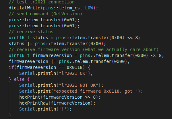
It tests the lr2021 connection by resetting it, waiting a bit, then sending a GetVersion command. It checks the result with the expected value, and if they match, we consider the lr2021 good.
Finally, to check the pyro channels, there's a basic interface over serial that lets me do a continuity test for a channel, arm the device, and fire a channel.
This is the interconnect testing section:
The flash and sd test:
lr2021 test:
lrtest_ppu
And finally, the pyro testing:
The firmware I'm writing for blueprint is just to test functionality to make sure everything got assembled correctly, since the actual flight firmware is illegal to publish (gnc code falls under ITAR) and that's going to take me months to write. If my reviewer has any questions about that, my dm's are open. The same goes for any questionable design decisions or bom optimi!
zations. I've already talked about it quite a bit with Kai.
12/29/2025 4:40 PM - Fixed the schematic like a lot a lot
Oh my goodness. I thought the schematic was fine. I was COMPLETELY WRONG. It was fine electrically, but it was kind of messy. I thought that it was fine, that it didn't really matter. I fixed basically everything. It is SO MUCH BETTER than I thought it would be and now I can actually read it. This is amazing. Thanks Kai Pereira for the wonderful suggestions, it's a lot better now. One minor thing that I also did was move the terminal blocks a bit so they didn't overhang the edge of the board, also one of his suggestions. It's a bit cleaner and less sketchy.
Schematic root
before:
after:
Sensors
before:
after:
RF
before:
after:
MCU
before:
after:
PPU
before:
after:
12/29/2025 4:48 PM - Added camera mosfet
On the ground, the cameras are by far the highest current draw device. Each one draws about 500ma just to be recording. I don't need them recording or even turned on while just idling on the pad or when it's on the ground, waiting to be recovered. Having that means that I need a bigger battery, which cuts into the mass budget.
Basically, I added in another pfet to control the high side power to the cameras. I would've used a nfet, but then the camera ground wouldn't match the vehicle ground, and that sounded like a recipe for disaster.
Here's the schematic for it (it's basically just another pyro high side switch, minus the sensing)
And the pcb area:
One thing that I really don't like about the current implementation but don't think I will fix (or really can) is that it cuts the 3v3 power plane almost in half. The battery power was routed on a THICK trace on that plane, and it goes across almost the entire board. However, it's only providing power to the rf stuff there, and maybe having a smaller trace carrying that will help isolate noise or something? I don't really know, but it is what it is, and they don't need that much current, so it's fine.
12/30/2025 1 PM - Decided to use an active antenna for gps
I was looking at antenna selection, and using a passive antenna is just really unappealing to me. There's the relatively high power lora transmit that's like 2cm away from the gps, which with unamplified signals from a passive antenna are like -130dbm, while the lora signals are about +22dbm. I'm just really worried about interference (yes I know that they're on different frequency bands, but still), so I'm going to use an active antenna.
To do that, I had to modify my schematic and board to have a few more passive components to power the active antenna. It's just an inductor, capacitor, and resistor.
Here's the new schematic for the gps:
And the updated pcb area:
12/30/2025 2:21 PM - Fixed micro sd part 3, came up with a name
Turns out I never really got the hand of the micro sd card, I used the flight computer tutorial as a reference to see which pullups I was missing (based off of some of the research I had done, it seemed pretty likely I was missing some).
I was missing a lot.
It wasn't very hard to add, just a pretty simple schematic edit and minor reroute of that area.
Here's the fixed schematic (for like the 3rd time):
And the pcb area:
The name of the project was the result of my friends and I brainstorming names, trying to come up with an acronym that sounded cool to us but also stood for something relevant. I'm pretty happy with the name we settled on. We decided what the name would be before figuring out the acronym entirely, since it was pretty clear we would be able to come up with one.
12/30/2025 2:30 PM - Wrote a README! Still need pictures
I put a lot of effort into my readme, especially the design reasoning section. There are a lot of expensive components that I'm using, that would make nearly zero sense for somebody just following the tutorial. That tutorial didn't exist when I started this project, and I actually have a flight vehicle being designed for this computer. It's actually going to fly on a guided rocket, which means the requirements for it are MUCH higher than a basic flight computer. Unfortunately, unless I explain that, the reviewers won't know why I picked what I did and my project will get rejected.
The only thing I have left to do in the readme is getting a render, which surely won't be too hard, right? (future me: IT SUCKED SO MUCH AND THAT WAS NOT GOOD)
Here's the readme:
12/30/2025 3:05 PM - Fought with Blender to get a render
I thought getting a render of my board wouldn't be that hard. I was wrong.
The first problem was that I was missing some 3d models of my components. Oh well, I just found some and added it. No problem!
Then I had to export the board. Very easy with pcb2blender. This is going great so far!
Then began the real work. It was SO HARD to get the board lit the way I wanted, and I ended up with way more lights than I thought I needed, then eventually replaced a bunch of them with area lights. Alright, it's lit, we're good, right?
NO! The exported board had the wrong materials for a bunch of stuff, and I had to figure out what texture everything was, was it metal or not, should it have scratches, so on and so forth.
After I got the textures fixed, you'd think I'd be done, right? Again, NO! For some stupid reason in my little pea sized brain, I decided I wanted an animation despite having forgotten how to use blender entirely. Needless to say, that was a REALLY STUPID IDEA. I spent way too long trying to get the camera paths looking good, and I know how I could do it way better now, but I really don't want to have to rerender it (8 hours of my rtx 3080 going crazy). It's good enough for me.
I got a pretty decent (in my opinion) render of the board:
And an "ok" (actually really bad now that I know how to do it better but oh well) animation which includes a rough model of the rocket it's going in:
animated render
Obviously the time for this journal does not include render time, I just suck that much at blender.
12/30/2025 3:11 PM - Minor finishing touches
I did some super minor finishing touches, like fixing the trace impedance on my vr_pa trace (thanks to mpk again for helping me figure out the impact of the vias on the trace's impedance) and adding the rendered picture to my readme. I did have to keep exporting and rerendering that picture because the colors didn't look right with the color management settings I had been picking (thanks a lot, Blender), but oh well.
Here's the (probably) final readme:
12/30/2025 8 PM - Final pass through the BoM
I went through the bom and tried to get the parts sourced from the cheapest source I could, and also MODIFIED IT FOR 2 BOARDS SINCE HACK CLUB IS AMAZING!!!!!
Thanks a lot to the review team for being patient with me while I tried to explain my design decisions as best as I could, and for letting me buy parts for 2.
New bom with everything added up:
LCSC saved me like $20 on the 2 gps's alone, it was crazy how much it saved (cut ~$40 off of the bom!)
1/1/2026 11 AM - Changed the flash chip
I was doing some math and checking over everything, and realized that the flash chip I had chosen was probably a little bit too small. It was 4 cents more per component (so 8 cents total) to get double the storage from the exact same model series as what I was using, so I changed the component.
Since it didn't let me when I submitted, this is for a project banner image (rather crappy but oh well):
I really hope that works
For reviewers, here's the cart screenshots of the parts that changed:
1/1/2026 6 PM - Added some silkscreen art + credits
I finally got around to doing what I had been meaning to from the start and adding some silkscreen art and credits. I especially want to thank @mpk for helping me through every step of the radio frequency design, and for supporting me through the process. If anybody deserves a place on the board, it's him. I'd also like to thank Kai Pereira for giving me some really good tips on how to improve my board, and for everybody on the blueprint team for answering my questions.
Thanks to everybody that helped me in any way along this process, it was quite the journey.
(no I'm not redoing my blender renders that was painful enough and it's close enough)
1/2/2026 - fix banner image (DUMMY ENTRY)
fix the banner image since it doesn't let you set that for some stupid reason. Please ignore this time and this journal entry, nothing was done (I'm not submitting for build review anyway and I set it as low as I could put it), this is literally just so I can have a banner image that doesn't look like trash