Self-made drone
I try to make as many components as possible myself.
Created by
 pelczvilmos
Tier 1
25 views
0 followers
 cubit010 ⚡
requested changes for Self-made drone ago
cubit010 ⚡
requested changes for Self-made drone ago
hey there!
please polish your frame with actual structural integrity in mind, i really don't see how that frame is going to fly with any reasonable structural integrity
once you do that, please also include an assembled view with how everything is going to be assembled
please also polish your flight controller and esc designs, you should use more fills, and polish a lot of the routing as well as using better components
i'm not sure what tools you have but no one usually has a good time trying to solder 0201 components, especially double sided pcbs. Please use components that can be more reasonably assembled
please also avoid the via-in-pads, make decoupling capacitors actually decouple something, make usb routing actually differential routing, and in general clean up everything and make it more polished
pelczvilmos
submitted Self-made drone for ship review ago
 Shadow
requested changes for Self-made drone ago
Shadow
requested changes for Self-made drone ago
Heya! Cool project but you need to design the frame yourself and not use an generative design, also I didn't understand your cart screenshots include a fc when you made one yourself , also use #printing-legion for 3D printing rather than jlc and also include the source files for cad
pelczvilmos
submitted Self-made drone for ship review ago
 CAN ⚡🚀
requested changes for Self-made drone ago
CAN ⚡🚀
requested changes for Self-made drone ago
Your journal needs to show the step-by-step process you took in making this project. Please break your larger journal entires into multiple smaller ones, show the steps you took, and explain it better.
pelczvilmos
submitted Self-made drone for ship review ago
pelczvilmos
added to the journal ago
I made the wiring diagram
So i draw the wiring diagram for the drone's electronic circuit. I searched a picture aboud every part and drew a line wor each wire connected. I never did this before, so i had to do a little research, how people do this. I used draw.io. After all it wasnt really hard.

cubit010 ⚡
requested changes for Self-made drone ago
hey!
i can't seem to find where your cad files are
once again as the previous reviewer mentioned, algorithmically generated structures are not allowed, please address that before resubmitting
please also follow the submission guidelines https://blueprint.hackclub.com/about/submission-guidelines and make sure your repo and project is up to code, and when you make changes, be sure to journal them
pelczvilmos
submitted Self-made drone for ship review ago
Shadow
requested changes for Self-made drone ago
Hey! A few things to note! Please go through submission guidelines and make sure to have everything!
Also, using AI for generative design for the case is NOT allowed! You need to make the frame for it yourself. Thanks
pelczvilmos
submitted Self-made drone for ship review ago
pelczvilmos
added to the journal ago
I made the frame
I made a frame model for the drone. It wasnt really hard, i watched a couple videos, how to make drone frames and found out, what dimensions are usually drone frames, and then designed the main parts (motor holder, fc/esc/vtx holder, battery holder). I hope it will be good.

 Iamalive 🚀
requested changes for Self-made drone ago
Iamalive 🚀
requested changes for Self-made drone ago
Great work so far! However I'm going to say that we can't fund some items in your BOM - specifically the drone frame and radio controller, as they are expensive premade parts that you can try making yourself. Try making those yourself, there are tons of guides online!
pelczvilmos
submitted Self-made drone for ship review ago
 PenguinMo
requested changes for Self-made drone ago
PenguinMo
requested changes for Self-made drone ago
Nice idea making your own drone but please expand your journal it seems you spent 20 hours making a schematic this seems very unreasonable and also please update your grant request to match cart screenshots and your BOM!
pelczvilmos
submitted Self-made drone for ship review ago
pelczvilmos
added to the journal ago
Little problem when creating BOM
I had a little problem when i made the BOM. When i got to do it i there was no LCSC part numbers next to the resistors and capacitors. That was because i used them from the KiCAD library and not downloaded the symbol from LCSC. Sadly I in the end realized i can download the JLCPCB library and it includes almost all of the components on LCSC. So i had to search and write in the part number for every component that didnt have one.

pelczvilmos
added to the journal ago
Choosing the parts for the drone
When choosing the parts i tried to choose the cheapest parts.
For the frame i needed at least a 3.5 inch one, because of the FC and ESC size. I also wanted one with propeller guards, so i choose DarwinFPV CineApe35 frame because it fits both of my needs and is the cheapest i could find. Also DarwinFPV is like the cheaper version of SpeedyBee (an other brand) in my experience.
For little things like the rubber shock dampening things, ST-Link, SH connectors i didnt have much conditions, just the basic dimension conditions for the connectors and rubber thingies and the compatibility one for the ST-Link. And then i choose the cheapest ones.
For the camera i choose also the cheapest i can find on aliexpress and fits my frame.
The VTX has may be a more famous, better quality brand, but it comes with cables and antennas, so in this kit its the cheaper choice amongst the others.
For motors i also choose the cheapest my frame supports, that happens to be made for this frame. And it comes in a 4 kit.
For props there isnt much price difference between them, so i choose one the internet recommend for 3.5 inch drones. And it comes in a 10 pair for 15 usd kit, so thats 0.75 cents/prop and there wasnt a much cheaper option.
For the ELRS RX i choose the Radiomaster XR1 nano 2.4ghz. I choose this because it meets the TX frequency and its the cheapest. I was thinking about a dual band one, but its more expensive and the TX doesnt support both frequency in its current form. In the future i will maybe upgrade it.
For the TX i choose the Radiomaster Pocket, because its the best value TX that support ELRS.
And i also need batteries for the TX (dont ask me why they dont include it with the TX) and unfortunately in my country its really hard to find 18650 batteries, so i have to order it from here.
Frame

The cam

ST-Link

Connectors

VTX

Rubber thingies

Motor

ELRS RX

Props

ELRS TX

Batteries

pelczvilmos
added to the journal ago
Problems with PCB designing
When i designed both PCB-s i had problems with the size. At first i was thinking about smaller board, because it goes in a small frame, but i just couldnt fit the parts, traces on it, thats why i choose the bigger, 30.5mm x 30.5mm mounting size. It was still a big struggle, but i managed to fit it on. Thats also the reason why i choose the 3.5 inch drone size, because its the smallest, that uses these mountings. Because i had problems with the traces i used the four layer pcb, so i had more space (even this way i had difficulties with routing even on the power layer and i also had to trace there some data lines. The power lines are probably a bit over power on the FC, because i used somewhere 0.5mm traces, with a gnd layer. On the ESC i used filled zoned for the main line, because it has really high peak current, because of the motors. I also placed the MOSFETS as close as possible to the pads for this reason. I also had a little problem next to the mounting holes, because some components i placed too close and because there a rubber shock dampening thing goes it can expand sideways when tightened on a bolt, so i placed every component as far as possible from those mounting holes.
The FC PCB design

The ESC PCB design

pelczvilmos
added to the journal ago
I laid down what I wanted
I love flying drones and engineering, so the idea came to my mind, that i should make one and make almost every electrical part i can do. So i began the research for the parts, how do i connect them together, the software for it. For software i choose betaflight, because its used the most as diy drone software and it has a lot of features and customizable possibilities. At first i was thinking about using an esp32 for the flight controller, because i used it before, and its very user friendly. But its not meant for this use case hardware wise and it doesnt support the official betaflight, just an open source frimware, that someone made and its very good, but doesnt include all the features betaflight has. So i choose the AT32 instead, which is basically a clone of the STM32. Its really meant for this, used in store bought FC-s and supports the official betaflight frimware, so its the best choice for this project. For the ESC microcontroller i chose also the AT32 chip, but a different version. I chose this because of the open source esc frimware and it also has almost 3 times higher clock speed than the STM32. I also wanted to include an ELRS reciever, mostly the gemini x one (dual-band), but sadly its not open source yet (or i just couldnt find it). Sadly a also couldnt make the single band one, because i couldnt find any frimware for it on github.


 zsharpminor ⚡
requested changes for Self-made drone ago
zsharpminor ⚡
requested changes for Self-made drone ago
You cannot buy a hot air gun with your grant. Additionally, we need your FULL cart screenshots from AliExpress showing EVERY item you're buying. Finally, we need WAY more journals showing how you made your project and proving it's your own work. Thanks.
pelczvilmos
submitted Self-made drone for ship review ago
Iamalive 🚀
requested changes for Self-made drone ago
Hey, I'm rejecting this based on a couple of things. For your bom(https://github.com/vili111111p/Self-made-drone/blob/main/BOM/FC.csv), please add every item you're planning on getting with your grant along with a link to where you'll buy it and its price. Additionally we won't be able to fund expensive pre-made items such as that drone and camera. Also, please take off the mini hot plate, as we don't allow users to buy things in the blueprint shop with their grant. For other matters, your journal is not detailed/goes into your design choices and how you got to your final pcb design. Right now it just gives the final product. Also, your pcb files should not be in a zip and you should upload each file individually. As it currently stands, this project is at most a tier 3.
pelczvilmos
submitted Self-made drone for ship review ago
pelczvilmos
added to the journal ago
i finished the esc PCB design
I finally finished the esc PCB design. At first i tought it will be easier, than the fc, because of the repeating pattern. I was partly right because i made two blocks and then i just mirrored the entire thing. The hard part was making one ECS fit on the quarter of the board. I used the 30.5x30.5 holes as on the fc to make a "stack". The power management circuit i tried to fit in a small block next to the battery connection pads. For connecting the Esc to fc i used the same connector as on fc. I'm happy with the results, its pretty good i think.
The pcb design.

pelczvilmos
added to the journal ago
I made the schematic for the ESC
So i made the schematic for the esc. It wasnt so difficult as the FC, but wasnt easy, because i had to make one esc and then just copy, paste and the other parts wasnt so difficult. It has 4 ESCs on one board. I choose the AT32F421 as the esc controller, because of the frimware support. I placed the current sensor also here, so it can measure the whole current consumption, like on store bought ESC-s. And i also included a pad for programmint the AT32's.
One of the ESCs

pelczvilmos
added to the journal ago
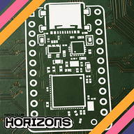
I made the FC pcb design
So now i made the PCB design for the FC. It has 4 layers. I couldn't do it better, it was still a big struggle. I choosed the 30.5x30.5 hole alignment, because its the biggest mounting standard for flight controllers in drones. For connecting the other parts to the FC i mostly used connectors for easy connections, better looks and for the pins, that are not used as much i just made a pad where i can solder wires. For production i was thinking about PCBA, but its VERY expensive so probably i will order the pcb and the components and i try to make it myself.
PCB desing

pelczvilmos
added to the journal ago
I made the schematic for the fc
So i researched what i want and how i want it. So i finally finished the schematic for the fc. I choose an AT32 for the main computing unit, becouse its like the industry standard for flight controllers. I also included an On Screen Display, a blackbox and IMU to be as good as a store bought one. Mostly i choosed the parts becouse of compatibility. For the blackbox i was thinking about using sd card, but becouse of the mechanical connection and the large space consumption i didnt want to use it.
As i remember i didnt have much problems with designing, just the usual, reading spending very long time with document reading, designing the schematic.
The schematic

pelczvilmos
started Self-made drone ago
12/14/2025 - I made the schematic for the fc
So i researched what i want and how i want it. So i finally finished the schematic for the fc. I choose an AT32 for the main computing unit, becouse its like the industry standard for flight controllers. I also included an On Screen Display, a blackbox and IMU to be as good as a store bought one. Mostly i choosed the parts becouse of compatibility. For the blackbox i was thinking about using sd card, but becouse of the mechanical connection and the large space consumption i didnt want to use it.
As i remember i didnt have much problems with designing, just the usual, reading spending very long time with document reading, designing the schematic.
The schematic
12/23/2025 1 PM - I made the FC pcb design
So now i made the PCB design for the FC. It has 4 layers. I couldn't do it better, it was still a big struggle. I choosed the 30.5x30.5 hole alignment, because its the biggest mounting standard for flight controllers in drones. For connecting the other parts to the FC i mostly used connectors for easy connections, better looks and for the pins, that are not used as much i just made a pad where i can solder wires. For production i was thinking about PCBA, but its VERY expensive so probably i will order the pcb and the components and i try to make it myself.
PCB desing
12/23/2025 4 PM - I made the schematic for the ESC
So i made the schematic for the esc. It wasnt so difficult as the FC, but wasnt easy, because i had to make one esc and then just copy, paste and the other parts wasnt so difficult. It has 4 ESCs on one board. I choose the AT32F421 as the esc controller, because of the frimware support. I placed the current sensor also here, so it can measure the whole current consumption, like on store bought ESC-s. And i also included a pad for programmint the AT32's.
One of the ESCs
12/26/2025 - i finished the esc PCB design
I finally finished the esc PCB design. At first i tought it will be easier, than the fc, because of the repeating pattern. I was partly right because i made two blocks and then i just mirrored the entire thing. The hard part was making one ECS fit on the quarter of the board. I used the 30.5x30.5 holes as on the fc to make a "stack". The power management circuit i tried to fit in a small block next to the battery connection pads. For connecting the Esc to fc i used the same connector as on fc. I'm happy with the results, its pretty good i think.
The pcb design.
1/7/2026 8 PM - I laid down what I wanted
I love flying drones and engineering, so the idea came to my mind, that i should make one and make almost every electrical part i can do. So i began the research for the parts, how do i connect them together, the software for it. For software i choose betaflight, because its used the most as diy drone software and it has a lot of features and customizable possibilities. At first i was thinking about using an esp32 for the flight controller, because i used it before, and its very user friendly. But its not meant for this use case hardware wise and it doesnt support the official betaflight, just an open source frimware, that someone made and its very good, but doesnt include all the features betaflight has. So i choose the AT32 instead, which is basically a clone of the STM32. Its really meant for this, used in store bought FC-s and supports the official betaflight frimware, so its the best choice for this project. For the ESC microcontroller i chose also the AT32 chip, but a different version. I chose this because of the open source esc frimware and it also has almost 3 times higher clock speed than the STM32. I also wanted to include an ELRS reciever, mostly the gemini x one (dual-band), but sadly its not open source yet (or i just couldnt find it). Sadly a also couldnt make the single band one, because i couldnt find any frimware for it on github.
1/7/2026 9:06 PM - Problems with PCB designing
When i designed both PCB-s i had problems with the size. At first i was thinking about smaller board, because it goes in a small frame, but i just couldnt fit the parts, traces on it, thats why i choose the bigger, 30.5mm x 30.5mm mounting size. It was still a big struggle, but i managed to fit it on. Thats also the reason why i choose the 3.5 inch drone size, because its the smallest, that uses these mountings. Because i had problems with the traces i used the four layer pcb, so i had more space (even this way i had difficulties with routing even on the power layer and i also had to trace there some data lines. The power lines are probably a bit over power on the FC, because i used somewhere 0.5mm traces, with a gnd layer. On the ESC i used filled zoned for the main line, because it has really high peak current, because of the motors. I also placed the MOSFETS as close as possible to the pads for this reason. I also had a little problem next to the mounting holes, because some components i placed too close and because there a rubber shock dampening thing goes it can expand sideways when tightened on a bolt, so i placed every component as far as possible from those mounting holes.
The FC PCB design
The ESC PCB design
1/7/2026 9:46 PM - Choosing the parts for the drone
When choosing the parts i tried to choose the cheapest parts.
For the frame i needed at least a 3.5 inch one, because of the FC and ESC size. I also wanted one with propeller guards, so i choose DarwinFPV CineApe35 frame because it fits both of my needs and is the cheapest i could find. Also DarwinFPV is like the cheaper version of SpeedyBee (an other brand) in my experience.
For little things like the rubber shock dampening things, ST-Link, SH connectors i didnt have much conditions, just the basic dimension conditions for the connectors and rubber thingies and the compatibility one for the ST-Link. And then i choose the cheapest ones.
For the camera i choose also the cheapest i can find on aliexpress and fits my frame.
The VTX has may be a more famous, better quality brand, but it comes with cables and antennas, so in this kit its the cheaper choice amongst the others.
For motors i also choose the cheapest my frame supports, that happens to be made for this frame. And it comes in a 4 kit.
For props there isnt much price difference between them, so i choose one the internet recommend for 3.5 inch drones. And it comes in a 10 pair for 15 usd kit, so thats 0.75 cents/prop and there wasnt a much cheaper option.
For the ELRS RX i choose the Radiomaster XR1 nano 2.4ghz. I choose this because it meets the TX frequency and its the cheapest. I was thinking about a dual band one, but its more expensive and the TX doesnt support both frequency in its current form. In the future i will maybe upgrade it.
For the TX i choose the Radiomaster Pocket, because its the best value TX that support ELRS.
And i also need batteries for the TX (dont ask me why they dont include it with the TX) and unfortunately in my country its really hard to find 18650 batteries, so i have to order it from here.
Frame
The cam
ST-Link
Connectors
VTX
Rubber thingies
Motor
ELRS RX
Props
ELRS TX
Batteries
1/7/2026 9:55 PM - Little problem when creating BOM
I had a little problem when i made the BOM. When i got to do it i there was no LCSC part numbers next to the resistors and capacitors. That was because i used them from the KiCAD library and not downloaded the symbol from LCSC. Sadly I in the end realized i can download the JLCPCB library and it includes almost all of the components on LCSC. So i had to search and write in the part number for every component that didnt have one.
2/10/2026 - I made the frame
I made a frame model for the drone. It wasnt really hard, i watched a couple videos, how to make drone frames and found out, what dimensions are usually drone frames, and then designed the main parts (motor holder, fc/esc/vtx holder, battery holder). I hope it will be good.
3/29/2026 - I made the wiring diagram
So i draw the wiring diagram for the drone's electronic circuit. I searched a picture aboud every part and drew a line wor each wire connected. I never did this before, so i had to do a little research, how people do this. I used draw.io. After all it wasnt really hard.