Synthesizer piano
A synthetizer piano with three octaves that uses a orpheus pico, PCM5100, LM4810.
Created by
 franklyneflorezn
Tier 3
16 views
0 followers
 Iamalive 🚀
requested changes for Synthesizer piano ago
Iamalive 🚀
requested changes for Synthesizer piano ago
Heyo, it looks like your bom costs and grant requested isn't matching? I assume that $20 is for printing legion - if so just attach the screenshot of the person printing your parts saying the shipping price. Thanks!
franklyneflorezn
added to the journal ago
e
i literally added that the 20$ extra dolars were for the shipment of the 3d case because there on colombia there is no printers from printers legion and the closest printers are from ee.uu, also i didnt requested 88 dollars i requested 73


franklyneflorezn
submitted Synthesizer piano for review ago
 1Mon ⚡
requested changes for Synthesizer piano ago
1Mon ⚡
requested changes for Synthesizer piano ago
you are requesting 88 dollars but your cart screenshots only total to around 55, please update this so it is consistant!
franklyneflorezn
submitted Synthesizer piano for review ago
Iamalive 🚀
requested changes for Synthesizer piano ago
Looks good! Just one final thing - I assume you're getting your case from printing legion, just make sure to raise your grant to include the price for shipping it!
franklyneflorezn
submitted Synthesizer piano for review ago
 Shaurya Bisht
requested changes for Synthesizer piano ago
Shaurya Bisht
requested changes for Synthesizer piano ago
funding amount and cart screenshots dont match up, only about 30 something in cart screenshots 60 in grant request?
franklyneflorezn
submitted Synthesizer piano for review ago
franklyneflorezn
added to the journal ago
Changed code, bom and readme
The first code I made already had basic audio generation, keyboard scanning, and screen setup, but it didnt had a proper menu system and some parts were messy. The reason for that is because I planned to adjust and improve the code once the kit and the PCB arrived to test it easier, but I had to do those changes earlier.
The first main improvement was clearly defining different states for the menu, like volume control, output selection, octave selection, and wave selection. I also added a debounce of about 0.15 seconds to avoid random or unintended button presses
I added visual feedback on the lcd(+1 octaves, 100% volumen, wave type). The menu now shows a 2×2 layout and the selected option is highlighted, so it’s easier to see where you are when navigating the menu using the keypad and u use the rotary encoder switch to select the option
I added settings storage using the microcontroller.nvm(Non-Volatile Memory). Things like volume, output mode, octave offset, and wave type are saved and loaded on startup, so the synthesizer keeps its settings
The output handling was improved so only one output is active at a time. when switching between midi, speakers, or line out, the audio is muted to avoid clicks or rare sounds and to prevent conflicts between outputs.
And to clarify i only need to buy the parts that are marked as they dont come in the kit and that i dont have in the bom file(i edited it), so i think i dont need to send screnshots of these parts because they come in the kit, and i think that the project actually is tier 3 not tier 4.

Iamalive 🚀
requested changes for Synthesizer piano ago
Your cart screenshots don't show every item you are planning to buy in your BOM. Additionally, this project would only be a tier 4 at best. Please add more journals that improve your project in some way!
franklyneflorezn
submitted Synthesizer piano for review ago
 PenguinMo
requested changes for Synthesizer piano ago
PenguinMo
requested changes for Synthesizer piano ago
ALL CAD needs to be in .step can you fix this please
franklyneflorezn
submitted Synthesizer piano for review ago
franklyneflorezn
added to the journal ago
code
okay, i think that this will be the last journal, i learned a lot in the path and i want to say that sorry if my english is bad, my native language is spanish not english and it is a bit bad but i try my best to write it.
and the last changes i made for this are that i added silkscreen,

then i created the code based on the guide and using ChatGPT (ill upgrade it and add all the functions i want to add once the parts arrive, because it’ll be easier to test)

i also made the .bom and uploaed all files to github
franklyneflorezn
added to the journal ago
created 3d case
i added one extra mounting hole because i think i will need to divide in two parts the 3d model because its size is more than 256 in x axe, and i started creating the 3d case following the hackpad case guide, but with wider borders and with the m3 head inserts below the pcb
and i made two holes for the usb and the jack output

after that i started creating the top plate using maths and the plate from hackpad tutorial


it looks very easy to do but it was harder for me. i’m very bad at 3D design lol.
franklyneflorezn
added to the journal ago
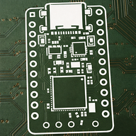
Ended pcb
First, i organized the switches in a piano configuration. then i routed the PCM5100, LM4810, PAM8403, and the capacitors. after that, I routed the switches and diodes. I deleted unnecessary text, routed the LCD screen, verified everything, and tried to make the pcb compact.


It wasn’t that difficult, but it was time-consuming.
franklyneflorezn
added to the journal ago
Final schematic
i fixed some errors, deleted the physical switch, organized and verified everything with ERC and Ia, so i think it will work perfectly i also viewed datashets of pam8403, and lm4810 to make sure it is right connected.


franklyneflorezn
added to the journal ago
ended schematics
changed Pam8304 for Pam0303 and i researched how to connect pins on pam8403 and lm4810, i connected first to two stereo speakers and second one to a 3mm jack and added one switch to switch with output will be used

then i created a pad to navigate on the menu, (now ill change the volume, effects, and octaves from there) and i think the schematic is ended

franklyneflorezn
added to the journal ago
making schematic
okay i first created the switch matrix with three octaves (6 rows and 7 columns) i wired them to the rasp berry pico


after that i wired the lcd screen(i think ill use a pot with a npn transistor to controll the back light, and i searched how to wire the pcm5100 because in the tutorial they didn't explain how to connect some pins and it took a lot of time

and i added two rotary encoders

franklyneflorezn
added to the journal ago
research
okay I want do a a three(21 notes and 15 sharp notes) or four(28 notes and 20 sharp notes) octaves syntethizer so it will have 36 or 48 switches, i want it to have built in speaker powered by DIP LM4861 or Pam8304 and one output auxiliar output powered by the LM4810, i also want one slider to change octaves and one for the volume, and i found this library to convert i2s to analog and i think that i can add effects like sustain.
https://github.com/elehobica/pico_audio_i2s_32b

i also learned a lot about audio generation, conversion from digital to analog, i learned the datashets of lm4810, pam5100 and lm4861 and saw some tutorials in youtube about them.
franklyneflorezn
started Synthesizer piano ago
12/9/2025 - research
okay I want do a a three(21 notes and 15 sharp notes) or four(28 notes and 20 sharp notes) octaves syntethizer so it will have 36 or 48 switches, i want it to have built in speaker powered by DIP LM4861 or Pam8304 and one output auxiliar output powered by the LM4810, i also want one slider to change octaves and one for the volume, and i found this library to convert i2s to analog and i think that i can add effects like sustain.
https://github.com/elehobica/pico_audio_i2s_32b
i also learned a lot about audio generation, conversion from digital to analog, i learned the datashets of lm4810, pam5100 and lm4861 and saw some tutorials in youtube about them.
12/11/2025 6 PM - making schematic
okay i first created the switch matrix with three octaves (6 rows and 7 columns) i wired them to the rasp berry pico
after that i wired the lcd screen(i think ill use a pot with a npn transistor to controll the back light, and i searched how to wire the pcm5100 because in the tutorial they didn't explain how to connect some pins and it took a lot of time
and i added two rotary encoders
12/11/2025 8 PM - ended schematics
changed Pam8304 for Pam0303 and i researched how to connect pins on pam8403 and lm4810, i connected first to two stereo speakers and second one to a 3mm jack and added one switch to switch with output will be used
then i created a pad to navigate on the menu, (now ill change the volume, effects, and octaves from there) and i think the schematic is ended
12/12/2025 9 AM - Final schematic
i fixed some errors, deleted the physical switch, organized and verified everything with ERC and Ia, so i think it will work perfectly i also viewed datashets of pam8403, and lm4810 to make sure it is right connected.
12/12/2025 3 PM - Ended pcb
First, i organized the switches in a piano configuration. then i routed the PCM5100, LM4810, PAM8403, and the capacitors. after that, I routed the switches and diodes. I deleted unnecessary text, routed the LCD screen, verified everything, and tried to make the pcb compact.
It wasn’t that difficult, but it was time-consuming.
12/13/2025 - created 3d case
i added one extra mounting hole because i think i will need to divide in two parts the 3d model because its size is more than 256 in x axe, and i started creating the 3d case following the hackpad case guide, but with wider borders and with the m3 head inserts below the pcb
and i made two holes for the usb and the jack output
after that i started creating the top plate using maths and the plate from hackpad tutorial
it looks very easy to do but it was harder for me. i’m very bad at 3D design lol.
12/14/2025 - code
okay, i think that this will be the last journal, i learned a lot in the path and i want to say that sorry if my english is bad, my native language is spanish not english and it is a bit bad but i try my best to write it.
and the last changes i made for this are that i added silkscreen,
then i created the code based on the guide and using ChatGPT (ill upgrade it and add all the functions i want to add once the parts arrive, because it’ll be easier to test)
i also made the .bom and uploaed all files to github
12/30/2025 - Changed code, bom and readme
The first code I made already had basic audio generation, keyboard scanning, and screen setup, but it didnt had a proper menu system and some parts were messy. The reason for that is because I planned to adjust and improve the code once the kit and the PCB arrived to test it easier, but I had to do those changes earlier.
The first main improvement was clearly defining different states for the menu, like volume control, output selection, octave selection, and wave selection. I also added a debounce of about 0.15 seconds to avoid random or unintended button presses
I added visual feedback on the lcd(+1 octaves, 100% volumen, wave type). The menu now shows a 2×2 layout and the selected option is highlighted, so it’s easier to see where you are when navigating the menu using the keypad and u use the rotary encoder switch to select the option
I added settings storage using the microcontroller.nvm(Non-Volatile Memory). Things like volume, output mode, octave offset, and wave type are saved and loaded on startup, so the synthesizer keeps its settings
The output handling was improved so only one output is active at a time. when switching between midi, speakers, or line out, the audio is muted to avoid clicks or rare sounds and to prevent conflicts between outputs.
And to clarify i only need to buy the parts that are marked as they dont come in the kit and that i dont have in the bom file(i edited it), so i think i dont need to send screnshots of these parts because they come in the kit, and i think that the project actually is tier 3 not tier 4.
1/22/2026 - e
i literally added that the 20$ extra dolars were for the shipment of the 3d case because there on colombia there is no printers from printers legion and the closest printers are from ee.uu, also i didnt requested 88 dollars i requested 73