Helio Hydration
Three-stage solar water disinfection (SODIS)-enhancing low-cost water bottle for NGO distribution to underserved and impoverished areas globally.
Created by
 loliipoppi 🚀
Tier 3
4 views
0 followers
loliipoppi 🚀
added to the journal ago
Ordered parts & soldered them
I ordered the necessary electrical components I needed for this project - the GUVA-S12SD UV sensor, the PCB, and the DS18B20 temperature sensor. Actually, when I got my PCBs, I realized that the temp sensor was already soldered on by accident, so I broke it off, but it made soldering the sensor I bought pretty difficult. I specifically bought a sensor that came pre-assembled onto a standard wire sleeve, so that was good. Hopefully it all works out. I also soldered the through-hole UV sensor - that one wasn't too bad. I put mounting screws on it but didn't really need it. Another thing is that I realized that I ordered the wrong PCB with PCBA, but I couldn't cancel it as it was already in production. That hurts... oh well. I'm hoping the PCB should still be fine.


loliipoppi 🚀
added to the journal ago
Built the bottle pt. 1
Today I built the bottle! Since I don't have a contact with a factory to manufacture custom plastic, I used a gallon water bottle that I cut the top off of (it can be used as a funnel :) ). I assembled the filter structure with M3 screws and used a biology fiber filter as the filter. It was really cool to see the snap fit working (even if only on one end). I had to 3D print the top of the indicator housing again since I forgot to hollow out a section, but after I did so, I put it on.
If you're wondering how I put the structures on top of the water bottle that I cut off, it's because I 3D printed an additional plate that has holes for the indicator and filter and sits on top of the bottle with good ol' hot glue. See below:

loliipoppi 🚀
added to the journal ago
3D printed the parts and worked on the BOM
3D printed them! It took me a while to make some edits to the CAD, because I had to cut some parts to make them production-ready. In addition, I realized I can't 3Dprint the bottle body, but I also can't manufacture it yet because I have no factory connections, so I think I'll just take a regular 2L bottle for now and cut off the top to make the top flat.
In addition, I updated the BOM to reflect all the electronic components + my PCB. Using PCBA about doubled the price per component, but I don't feel like hand SMD soldering this time (especially with 0402 :P). Took me a while but finally got an accurate quote for everything.
3D slicer:

loliipoppi 🚀
added to the journal ago
Set cover image
Here's my new cover image! I chose the picture of the master assembly for now, but a logo would also be cool as this was previously going to be developed into a company.
Actually, I take that back. A logo seems pretty cool :)

loliipoppi 🚀
added to the journal ago
Wrote readme and bom
To finish off my project, I wrote a readme and developed my BOM. Below is a picture of my BOM (I tried to optimize costs as much as possible as it's for mass distribution to underserved communities:

The readme and BOM are now in my github: github.com/jaydenaleung/helioHydration
loliipoppi 🚀
added to the journal ago
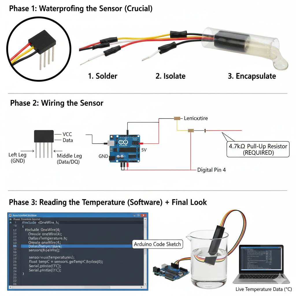
Wrote the code
The code is structured very simply. The MCU continuously runs a formula that accumulates L(t), the number of log reductions of E. coli, as a function of the UV intensity (measured by the photodiode) and the water temperature (measured by the temperature sensor). Once the process begins, the MCU takes in these inputs and calculates the current L(t) according to the following function, where delta t is the time interval between calculations.

This function is based on the following theoretical function:

Once the L(t) reaches 3 - once there are three log reductions of E. coli (99.9% of E. coli destroyed) - the process finishes.
The photodiode is measured by reading an analog input, and the temperature sensor is read with the DallasTemperature.h and OneWire.h Arduino libraries.
Below is a snippet of the code implementation:

loliipoppi 🚀
added to the journal ago
Built the body and full assembly
After finishing the indicator and filter, I built the body of the bottle. This will be a part-paraboloid bottle (the rest is cylindrical) with the following specifications:
120mm diameter
Parabola stops 100mm from the ground
A height appropriate for the above parameters
Bottle cross-section:

To determine the equation-driven shape and the unknown bottle dimensions, I performed the following calculations:
Fitting the curve shows us that y = (1/36)x^2 is the only equation that fits. The focus of the parabola is at (0,9), which is appropriate to heat the sediment at the bottom with the focused UV radiation.
Write the integral for the volume of the bottle by revolution and solve for the height h, where d is the maximum diameter of the bottle (120mm) and a is the parabolic coefficient (1/36):

We get 226.83887 mm as h.
The following integral (with h plugged in) confirms that the volume of the bottle is 2L (2000000 mm^3 = 2 L).

I then used this equation and these dimensions to build the body of the bottle. Note that 1/3 of the parabola from the ground is covered with a black surface to trap the heat in for the sediment. The rest of the parabola is covered with a reflective material to reflect the UV rays. The rest of the bottle is made with clarified polypropylene (PP) for maximum UV transparency while maintaining bottle durability/breakdown and cost.
Final model (the transparent parts indicate the transparency of the bottle):

loliipoppi 🚀
added to the journal ago
Built indicator housing, PCB, and schematic
After sourcing parts for the indicator, I needed to design the PCB, schematic, and housing. I started with the schematic and PCB, specifically with making custom symbols and footprints. I downloaded them for the DS18B20 temperature sensor, but had to look at the datasheet/online guides for the GUVA-S12SD UV sensor to make the schematic. For the footprint, the marketplace listing did not provide any information aside from being 11x27mm, so I had to eyeball the sizes of the mounting holes, chips, and the actual sensor relative to the 1mm diameter I/O pin holes. It wasn't a great way to measure things, but it will have to do for now, and I made the holes on the footprint slightly larger than what I estimated them to be to be safe. The final footprint I made was just a row of 4 pins to connect an ISP Programmer to the onboard ATMega328P (I'd chosen to do that rather than mount a whole ESP32 or Arduino on the PCB).

I used a youtube video guide (the creator was a good teacher, gave him a sub) to work the standalone ATMega328P chip and allow it to be programmable. That was the bulk of the work on the schematic, but I also had to look at some online guides for hooking up the other modules. Turns out the DS18B20 - the temp sensor - has two modes, one where you power it regularly, but also 'parasite mode,' which harvests energy from the digital pin and needs not be directly powered. Not as stable, but still quite cool.
My final schematic:

I continued to design the PCB, keeping in mind that the UV sensor should be positioned in the middle. To accommodate this, and the large voltage converter, I had to reroute the PCB once to make space to "fold down" the voltage converter.
PCB:

After this, I exported the main PCB and the GUVA-S12SD footprint PCB from KiCad to a STEP file that I imported into SolidWorks to make the housing. It wasn't extremely difficult to make a case, except that I had some trouble deciding how I would mount the PCB on it with an offset for the temperature sensor wires. For the top, I decided to use a revolved extrude so that the sunlight would be able to hit the UV sensor while still keeping the taller chip components in the case. The angle from the edge to the sensor was less than 15 deg consistently.


loliipoppi 🚀
added to the journal ago
Designed housing for indicator & sourced parts
It took me WAY too long to source parts for a UV sensor multi-angle photodiode (it kept giving me UV LED) and to figure out how to work a temperature sensor (looks like a transistor but apparently the plastic senses the heat). I eventually decided to create a housing for a PCB that would connect both modules to a cheap microcontoller. The housing would sit directly above the tank so the temperature probe would easily reach the water and the photodiode could be placed face-up.
Here's what the photodiode looks like:

Here's what the temperature sensor looks like (somewhat - I tried generating an image with Gemini):

](https://blueprint.hackclub.com/user-attachments/representations/redirect/eyJfcmFpbHMiOnsiZGF0YSI6Njc2MDcsInB1ciI6ImJsb2JfaWQifX0=--03bdc1c0a355c569da0e577bd565697df55da796/eyJfcmFpbHMiOnsiZGF0YSI6eyJmb3JtYXQiOiJqcGVnIiwicmVzaXplX3RvX2xpbWl0IjpbMjAwMCwyMDAwXSwiY29udmVydCI6IndlYnAiLCJzYXZlciI6eyJxdWFsaXR5Ijo4MCwic3RyaXAiOnRydWV9fSwicHVyIjoidmFyaWF0aW9uIn19--9a17bdfa40edbe8d53adc10208035f8ccf5fb8ef/image0%20(1).jpeg)

The two parts would be held together by clips designed below:

I learned CAD in Onshape, but I wanted to try out SolidWorks for some more professional experience. The sketches were mostly like Onshape, but the interface felt more clunky and unclear, and the app often crashed (save your work... 🥲). I spent an unnecessary amount of time trying to figure out how to merge and union two parts in separate files and how to rotate things in assembly. I found out later that most people use mates to move items, but this just confused me more, as it was a lot simpler in Onshape. What was even MORE was that I found out after, when I was done, that there WAS a triad option to move and rotate objects, although not by specific value - but people usually free rotated to about where they wanted it and THEN mated it. That would have made my life so much easier... 😭.
Anyhoo, I finished it, exported it to Blender, and found out Blender rendering is kind of difficult (there goes 45 minutes). But I learned some Blender, which is good!
Some render pictures:


loliipoppi 🚀
added to the journal ago
Researched methods for filtration and indication
Before diving into CAD and other designs for the filter and the indicator, I needed to do some research on what would be the most effective methods first. After conversing with ChatGPT (as it had a lot of outside knowledge I personally didn't have access to), we came up with the following plan:
Filter:
Requirements:
- Nanoparticle filtering capability - microfiber or more precision filters
- Non-leeching - use fiber or a non-leeching metal
- Reusable - use an easily backflushable or cleanable filter
High-level Plan:
- Dual-stage filtering approach - first level for macroparticle filtering, second level for nanoparticle filtering
- Stage 1 - cloth/fabric filtration
- Cleaning method: washable
- NOTE: must follow a highly durable and reusable filter design (polyester or nylon mesh over cotton, see above)
- Stage 2 - ceramic filter
- Cleaning method: scrubbable with abrasive
- Higher durability than hollow fiber membranes
Deliverables:
- CAD model of entire filter in Solidworks, with exploded view
- Diagram depiction of exploded view with descriptions of each stage
- Analytical/bounded & literature-backed metrics (see below)


Indicator:
Requirements:
- Be able to accurately detect the level of harmful fecal coliform bacteria present by measuring the level of E. coli (general indicator of fecal contamination)
- “In 2022, globally, at least 1.7 billion people use a drinking water source contaminated with faeces. Microbial contamination of drinking-water as a result of contamination with faeces poses the greatest risk to drinking-water safety.” —WHO
- Cannot directly, quickly, and cheaply measure bacteria in the field, so must use UV + temperature sensors to calculate the expected readiness instead, backed by WHO research metrics of UV/temp correlation with bacterial inactivation
- Non leeching detector material
- Low cost and safe electronics - use IC instead of breakout board, shield wires from touching water
- Reusable detection method
High-level Plan:
- Implement UV Dose + Temperature (Synergistic) model
- Calculate bacteria log-reductions using established WHO metrics and correlations of temp/UV with bacterial inactivation
- Use ultra-low-cost custom electronics
- Only need a temperature sensor (NTC thermistor), UV sensor (UV photodiode), MCU, LED
Deliverables:
- CAD, PCB/schematic, and firmware code
- A developed computational calculation that takes in data from photodiode and temperature sensor and turns it into the effective dose Deffective
- Sourced parts and low-cost BOM
I started on deliverable #2, and after reading literature, I used ChatGPT to help me derive a formula for the number of log reductions for a given time using data from a photodiode and temperature sensor. Solving the differential equation for bacterial decay (taking into account UV exposure and temperature):

We got:

...although I still need to read more literature to find the sigma value we should use.
loliipoppi 🚀
started Helio Hydration ago
1/2/2026 12 PM - Researched methods for filtration and indication
Before diving into CAD and other designs for the filter and the indicator, I needed to do some research on what would be the most effective methods first. After conversing with ChatGPT (as it had a lot of outside knowledge I personally didn't have access to), we came up with the following plan:
Filter:
Requirements:
- Nanoparticle filtering capability - microfiber or more precision filters
- Non-leeching - use fiber or a non-leeching metal
- Reusable - use an easily backflushable or cleanable filter
High-level Plan:
- Dual-stage filtering approach - first level for macroparticle filtering, second level for nanoparticle filtering
- Stage 1 - cloth/fabric filtration
- Cleaning method: washable
- NOTE: must follow a highly durable and reusable filter design (polyester or nylon mesh over cotton, see above)
- Stage 2 - ceramic filter
- Cleaning method: scrubbable with abrasive
- Higher durability than hollow fiber membranes
Deliverables:
- CAD model of entire filter in Solidworks, with exploded view
- Diagram depiction of exploded view with descriptions of each stage
- Analytical/bounded & literature-backed metrics (see below)


Indicator:
Requirements:
- Be able to accurately detect the level of harmful fecal coliform bacteria present by measuring the level of E. coli (general indicator of fecal contamination)
- “In 2022, globally, at least 1.7 billion people use a drinking water source contaminated with faeces. Microbial contamination of drinking-water as a result of contamination with faeces poses the greatest risk to drinking-water safety.” —WHO
- Cannot directly, quickly, and cheaply measure bacteria in the field, so must use UV + temperature sensors to calculate the expected readiness instead, backed by WHO research metrics of UV/temp correlation with bacterial inactivation
- Non leeching detector material
- Low cost and safe electronics - use IC instead of breakout board, shield wires from touching water
- Reusable detection method
High-level Plan:
- Implement UV Dose + Temperature (Synergistic) model
- Calculate bacteria log-reductions using established WHO metrics and correlations of temp/UV with bacterial inactivation
- Use ultra-low-cost custom electronics
- Only need a temperature sensor (NTC thermistor), UV sensor (UV photodiode), MCU, LED
Deliverables:
- CAD, PCB/schematic, and firmware code
- A developed computational calculation that takes in data from photodiode and temperature sensor and turns it into the effective dose Deffective
- Sourced parts and low-cost BOM
I started on deliverable #2, and after reading literature, I used ChatGPT to help me derive a formula for the number of log reductions for a given time using data from a photodiode and temperature sensor. Solving the differential equation for bacterial decay (taking into account UV exposure and temperature):

We got:

...although I still need to read more literature to find the sigma value we should use.
1/2/2026 1 PM - Designed & CADed the filter
Before CADing, I used my Kindle Scribe to design the filter. I followed a two-step approach where the first step included a clamp to hold the fiber filter in place, and the next step included an enclosed chamber for a cylindrical ceramic filter.
.jpeg)

The two parts would be held together by clips designed below:

I learned CAD in Onshape, but I wanted to try out SolidWorks for some more professional experience. The sketches were mostly like Onshape, but the interface felt more clunky and unclear, and the app often crashed (save your work... 🥲). I spent an unnecessary amount of time trying to figure out how to merge and union two parts in separate files and how to rotate things in assembly. I found out later that most people use mates to move items, but this just confused me more, as it was a lot simpler in Onshape. What was even MORE was that I found out after, when I was done, that there WAS a triad option to move and rotate objects, although not by specific value - but people usually free rotated to about where they wanted it and THEN mated it. That would have made my life so much easier... 😭.
Anyhoo, I finished it, exported it to Blender, and found out Blender rendering is kind of difficult (there goes 45 minutes). But I learned some Blender, which is good!
Some render pictures:


1/2/2026 3 PM - Designed housing for indicator & sourced parts
It took me WAY too long to source parts for a UV sensor multi-angle photodiode (it kept giving me UV LED) and to figure out how to work a temperature sensor (looks like a transistor but apparently the plastic senses the heat). I eventually decided to create a housing for a PCB that would connect both modules to a cheap microcontoller. The housing would sit directly above the tank so the temperature probe would easily reach the water and the photodiode could be placed face-up.
Here's what the photodiode looks like:

Here's what the temperature sensor looks like (somewhat - I tried generating an image with Gemini):

.

I used a youtube video guide (the creator was a good teacher, gave him a sub) to work the standalone ATMega328P chip and allow it to be programmable. That was the bulk of the work on the schematic, but I also had to look at some online guides for hooking up the other modules. Turns out the DS18B20 - the temp sensor - has two modes, one where you power it regularly, but also 'parasite mode,' which harvests energy from the digital pin and needs not be directly powered. Not as stable, but still quite cool.
My final schematic:

I continued to design the PCB, keeping in mind that the UV sensor should be positioned in the middle. To accommodate this, and the large voltage converter, I had to reroute the PCB once to make space to "fold down" the voltage converter.
PCB:

After this, I exported the main PCB and the GUVA-S12SD footprint PCB from KiCad to a STEP file that I imported into SolidWorks to make the housing. It wasn't extremely difficult to make a case, except that I had some trouble deciding how I would mount the PCB on it with an offset for the temperature sensor wires. For the top, I decided to use a revolved extrude so that the sunlight would be able to hit the UV sensor while still keeping the taller chip components in the case. The angle from the edge to the sensor was less than 15 deg consistently.


1/11/2026 4 PM - Built the body and full assembly
After finishing the indicator and filter, I built the body of the bottle. This will be a part-paraboloid bottle (the rest is cylindrical) with the following specifications:
120mm diameter
Parabola stops 100mm from the ground
A height appropriate for the above parameters
Bottle cross-section:

To determine the equation-driven shape and the unknown bottle dimensions, I performed the following calculations:
Fitting the curve shows us that y = (1/36)x^2 is the only equation that fits. The focus of the parabola is at (0,9), which is appropriate to heat the sediment at the bottom with the focused UV radiation.
Write the integral for the volume of the bottle by revolution and solve for the height h, where d is the maximum diameter of the bottle (120mm) and a is the parabolic coefficient (1/36):

We get 226.83887 mm as h.
The following integral (with h plugged in) confirms that the volume of the bottle is 2L (2000000 mm^3 = 2 L).

I then used this equation and these dimensions to build the body of the bottle. Note that 1/3 of the parabola from the ground is covered with a black surface to trap the heat in for the sediment. The rest of the parabola is covered with a reflective material to reflect the UV rays. The rest of the bottle is made with clarified polypropylene (PP) for maximum UV transparency while maintaining bottle durability/breakdown and cost.
Final model (the transparent parts indicate the transparency of the bottle):

1/11/2026 5 PM - Wrote the code
The code is structured very simply. The MCU continuously runs a formula that accumulates L(t), the number of log reductions of E. coli, as a function of the UV intensity (measured by the photodiode) and the water temperature (measured by the temperature sensor). Once the process begins, the MCU takes in these inputs and calculates the current L(t) according to the following function, where delta t is the time interval between calculations.

This function is based on the following theoretical function:

Once the L(t) reaches 3 - once there are three log reductions of E. coli (99.9% of E. coli destroyed) - the process finishes.
The photodiode is measured by reading an analog input, and the temperature sensor is read with the DallasTemperature.h and OneWire.h Arduino libraries.
Below is a snippet of the code implementation:

1/11/2026 7:06 PM - Wrote readme and bom
To finish off my project, I wrote a readme and developed my BOM. Below is a picture of my BOM (I tried to optimize costs as much as possible as it's for mass distribution to underserved communities:

The readme and BOM are now in my github: github.com/jaydenaleung/helioHydration
1/11/2026 7:09 PM - Set cover image
Here's my new cover image! I chose the picture of the master assembly for now, but a logo would also be cool as this was previously going to be developed into a company.
Actually, I take that back. A logo seems pretty cool :)

1/12/2026 - 3D printed the parts and worked on the BOM
3D printed them! It took me a while to make some edits to the CAD, because I had to cut some parts to make them production-ready. In addition, I realized I can't 3Dprint the bottle body, but I also can't manufacture it yet because I have no factory connections, so I think I'll just take a regular 2L bottle for now and cut off the top to make the top flat.
In addition, I updated the BOM to reflect all the electronic components + my PCB. Using PCBA about doubled the price per component, but I don't feel like hand SMD soldering this time (especially with 0402 :P). Took me a while but finally got an accurate quote for everything.
3D slicer:

1/19/2026 - Built the bottle pt. 1
Today I built the bottle! Since I don't have a contact with a factory to manufacture custom plastic, I used a gallon water bottle that I cut the top off of (it can be used as a funnel :) ). I assembled the filter structure with M3 screws and used a biology fiber filter as the filter. It was really cool to see the snap fit working (even if only on one end). I had to 3D print the top of the indicator housing again since I forgot to hollow out a section, but after I did so, I put it on.
If you're wondering how I put the structures on top of the water bottle that I cut off, it's because I 3D printed an additional plate that has holes for the indicator and filter and sits on top of the bottle with good ol' hot glue. See below:

2/23/2026 - Ordered parts & soldered them
I ordered the necessary electrical components I needed for this project - the GUVA-S12SD UV sensor, the PCB, and the DS18B20 temperature sensor. Actually, when I got my PCBs, I realized that the temp sensor was already soldered on by accident, so I broke it off, but it made soldering the sensor I bought pretty difficult. I specifically bought a sensor that came pre-assembled onto a standard wire sleeve, so that was good. Hopefully it all works out. I also soldered the through-hole UV sensor - that one wasn't too bad. I put mounting screws on it but didn't really need it. Another thing is that I realized that I ordered the wrong PCB with PCBA, but I couldn't cancel it as it was already in production. That hurts... oh well. I'm hoping the PCB should still be fine.

