Blackie
Blackie – a macropad based on the STM32F031K6Ux. This is the most advanced project I’ve ever made, and I hope you’ll enjoy following my journey.
Created by
 Jadamek1337
3 views
0 followers
Timeline
Jadamek1337
added to the journal ago
Final Schematic
This is how it looks like ;)

Jadamek1337
added to the journal ago
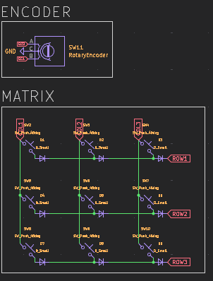
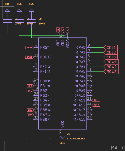
Made Encoder and Matrix
At the end of the schematic, I worked on the keyboard matrix for the mechanical keyboard and the encoder.
The keyboard will use Cherry switches, and for the encoder I chose the EC11.
This part is pretty standard for mechanical keyboards and didn’t cause any major issues.
Jadamek1337
added to the journal ago
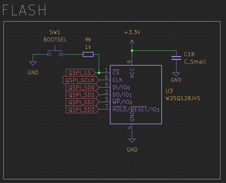
Made QSPI Flash
I set up the QSPI Flash for the project.
QSPI Flash is basically extra memory that’s super fast because it uses four data lines instead of one. It’s perfect for storing stuff like firmware or big tables that the MCU needs to read quickly.
This way, I can have more memory without slowing anything down, which is really handy for this type of projects.
Jadamek1337
added to the journal ago
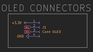
Made OLED Connectors
Added OLED connectors. Since I want the OLED screen to sit higher, I used regular female headers on pins positioned higher to make the setup look cleaner and more organized.
-
4 pins for connection
-
5.1 kΩ pull-up resistors on each pin
This was a simple step, but it improves the overall layout and appearance.
Jadamek1337
added to the journal ago
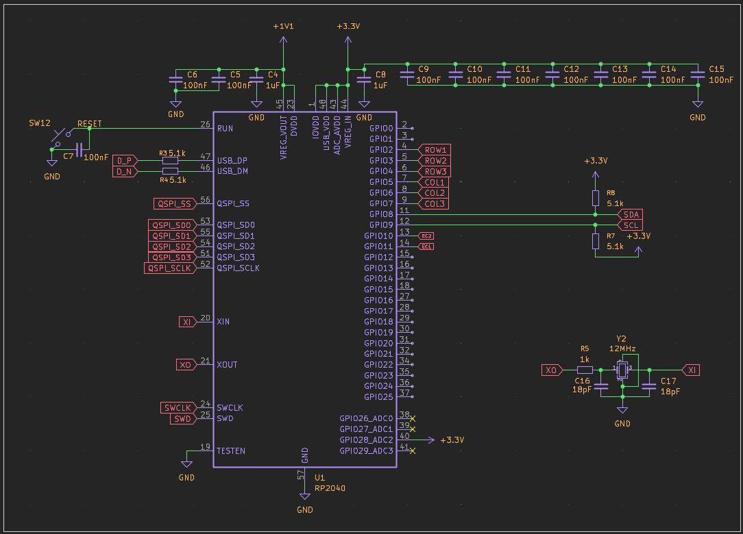
MCU Setup
At this stage, I got the RP2040 MCU up and running. Here's what I did:
-
Connected the MCU and added all the essential components.
-
Added capacitors and a 12 MHz oscillator to stabilize the circuit.
-
Added pins for easy connections.
The process was straightforward, and everything is now ready for the next steps of the project.
Jadamek1337
added to the journal ago
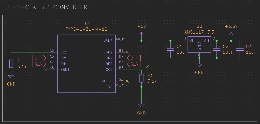
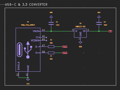
Made USB-C and 3.3V Converter
Note: I had to change the microcontroller to the rp2040 because the ESP does not support KMK/QMK.
Current Progress
- Created a new USB-C power supply with programming functionality.
- Added an AMS1117 voltage converter to 3.3V.
- Added 10µF capacitors to reduce electrical interference.
Jadamek1337
added to the journal ago
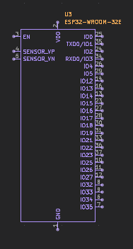
MCU decision
I decided to use ESP32-WROOM-32E instead of an STM32.
Reasons
- Dual-core CPU up to 240 MHz
- Built-in Wi-Fi and Bluetooth
- 4 MB flash, sufficient SRAM
- Wide set of peripherals (GPIO, UART, SPI, I²C, ADC, PWM)
- Easy OTA updates and good software support
ESP32 vs STM32 (brief)
| Feature | ESP32 | STM32 |
|---|---|---|
| Wireless | Built-in | External module needed |
| Performance | Higher | Lower (typical) |
| Power use | Higher | Lower |
| Real-time | Moderate | Better |
ESP32 fits connected and IoT-focused designs, while STM32 is better for low-power and strict real-time applications.
Jadamek1337
added to the journal ago
First Fail
I discovered a serious mistake — my STM will not work with QMK/KMK, so I have to change it.
It’s unfortunate because all the work will go to waste, and I need to use a different chip, such as the RP2040.
Jadamek1337
added to the journal ago
Made PCB Schematic
I managed to complete the entire PCB schematic.
It wasn’t that difficult, and the process was very intuitive. Along the way, I gained a much better understanding of how the components interact with each other and how careful planning affects the reliability of the final design.

Jadamek1337
added to the journal ago
Started making PCB!
Now that I had familiarized myself with the architecture, I started designing the PCB in KiCad.
I decided that the keyboard would be powered via USB-C and connected to the STM through an AMS1117 voltage regulator.
- I also worked on the encoder, the OLED display, and other essential components.
Jadamek1337
added to the journal ago
Basics!!!
In the first stage, I focused on what I would need to create a macropad.
It will not be an ordinary macropad; it will be more in the professional category, without using the typical off-the-shelf microcontrollers.
I reviewed datasheets and started looking into how decoupling capacitors work and what techniques are used.
Jadamek1337
started Blackie ago