USB Hub
A tiny USB hub that uses the SL2.1 IC and MCP2221A
Created by
 Rudy 🚀
Tier 4
19 views
0 followers
 alexren ⚡🚀
approved USB Hub ago
alexren ⚡🚀
approved USB Hub ago
Tier approved: 4
Grant approved: $44.88
amazing hub wow nice job rudy
Rudy 🚀
submitted USB Hub for ship review ago
 samliu ⚡🚀
requested changes for USB Hub ago
samliu ⚡🚀
requested changes for USB Hub ago
Hey! Please make sure you fully check over the submission guidelines (https://blueprint.hackclub.com/about/submission-guidelines). Go through the list yourself and check it off one by one.
Rudy 🚀
submitted USB Hub for ship review ago
Rudy 🚀
added to the journal ago
Case Design
22/01/26
I worked on designing a case for the USB Hub today.
Started off my correcting the 3D model placements in kicad and then exported them into Fusion360.
Now the problem I faced here was that each part was an individual component and I couldn't move them all together at once. I tried saving the board and then importing it into a new project but still I could only individually select components. The solution I found was to assign all these components a rigid body set, that basically makes is so that when you move one component the rest follow.
Now designing the case was pretty straightforward as I aimed to be as minimal as possible.
I started off by designing the bottom plate first, it was a very simple very thin plate with countersunk holes for an M2 screw.
For the top part of the case I just designed a rectangle and then projected the USB port's geometry on it and cut it out with some offset.
Inside the top part I added these 4 pillars type thing inside which I can later fit some heatset M2 inserts to screw onto and secure the bottom plate and PCB.
The finished case look something like this-
Time Spent: 1.5 Hours
 PenguinMo
requested changes for USB Hub ago
PenguinMo
requested changes for USB Hub ago
Nice USB hub but this is not really a tier 4 right now please consider adding some code or just increasing the overall complexity of this project, this is all you should need to fix. Can't wait to see you build this!
Rudy 🚀
submitted USB Hub for ship review ago
Rudy 🚀
added to the journal ago
Rev 2
9/01/26
Decided to add some more features to the USB hub. I figured why not add an onboard USB to UART chip so I can just use the hub as a debugging tool, and so I began my research and found the MCP2221A.
The MCP2221A is a small USB 2.0 to I2C/UART convertor chip by microchip which came in a small 4x4 QFN package.
I also decided to add another SL2.1S IC and daisy chain it with the first one to get a total of 7 downstream USB ports, out of those 7 downstream ports I used 6 for USB and 1 for the MCP2221.
Wiring up the MCP2221 was pretty straightforward, the datasheet was also helpful and I found that the 4 GPIO pins have a default function as indication for activity and so I wired those up to some LEDs.
Now the UART/I2C indicators go low when they sense activity, but the USB_CFG goes high/low depending on if the USB is successfully configured or in suspend mode.
Moving onto the PCB, it was pretty clear to me that I'd have to start over again, and so I deleted everything I originally had and started fresh with a new layout.
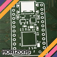
I went with a symmetric layout (kinda) with 4 USB-A ports on one side and 4 USB-C ports on the other side.
After that I just routed everything and fixed the pinouts in the schematics based on which port was the closest, and in the end I ended up with this.
Also decided to add mounting holes on the PCB as you can see, decided I might need them in the future if I plan on making a case.
Also spent a few minutes just updating the BOM and getting prices from lcsc and JLC.
Time Spent: 3 Hours
 Iamalive 🚀
requested changes for USB Hub ago
Iamalive 🚀
requested changes for USB Hub ago
Hey, at the moment this project can only be a tier 5 at best. Can you try to do more/add complexity to your project in some way? Waybe by designing a cad case or writing code! Thanks!
Rudy 🚀
submitted USB Hub for ship review ago
 zsharpminor ⚡
requested changes for USB Hub ago
zsharpminor ⚡
requested changes for USB Hub ago
This looks good, but similar to your other projects, your journal images are broken, and we need your full LCSC cart screenshot! Finally, please make your BOM a .csv. Thanks! :D
Rudy 🚀
submitted USB Hub for ship review ago
Rudy 🚀
added to the journal ago
Journal
USB Hub
27/12/25
I was pretty bored and ran out of ideas today so I decided to speedrun a USB Hub; to be honest I have been in need of a usb hub for a LONG time but always procrastinated making one (since onboard btw).
I decided to use the SL2.1S chip because it's a fairly easy IC to use; requires no external crystals and have 4 downstream facing ports which is good enough for me (though I did spent a lot of time looking at alternatives from microchip and ti but they were too overkill for what I needed).
I had to first translate the whole datasheet because it was originally in Chinese; the datasheet says that it does require and external crystal to work but I referred to some designs online and they seem to be working fine without one, so I went ahead with my schematics and connected xin to gnd.
I added a 100nf and 1uF capacitor for each power pin (although this was probably not required); after this I went ahead with my PCB design (the fun part!!); started off by assigning net classes and color coding them to give me a better view as usual.
Layout was pretty easy as this PCB hardly had any components; I went with a 50x20mm board to keep the hub as tiny as possible. Here are some pictures of the routing process
^This was the finished board, I went with 2 layers and routed all the data and cc traces on top, poured ground on bottom and routed power; I did make sure to not have any splits in the ground plane under the data pairs!
And another thing I added was a power indicator led; its just a green led connected to the vbus to indicate power detection. For this I added two 5.1k resistors in series to limit current which adds up to 10.2k ohm in series with the LED. Now you may think that this is way to much and that the led would barely glow, but you'd be wrong; 0402 LEDs are super efficient and super bright, even at 10K resistor in series at 5v the LED is bright enough to be seen in a lit room.
Oh and yeah the reason I went with two 5.1k resistors in series instead of just one 10k resistor was to optimize the BOM; even though the project is pretty cheap, why use more components than needed right.
After this I spent a couple of minutes adding some basic silkscreen and assigning lcsc parts; generating the BOM with prices and finally setting up a github repository.
Anywho this is how the final board looks like!
Time Spent: 3.5 Hours
Rudy 🚀
started USB Hub ago
12/27/2025 - Journal
USB Hub
27/12/25
I was pretty bored and ran out of ideas today so I decided to speedrun a USB Hub; to be honest I have been in need of a usb hub for a LONG time but always procrastinated making one (since onboard btw).
I decided to use the SL2.1S chip because it's a fairly easy IC to use; requires no external crystals and have 4 downstream facing ports which is good enough for me (though I did spent a lot of time looking at alternatives from microchip and ti but they were too overkill for what I needed).
I had to first translate the whole datasheet because it was originally in Chinese; the datasheet says that it does require and external crystal to work but I referred to some designs online and they seem to be working fine without one, so I went ahead with my schematics and connected xin to gnd.
I added a 100nf and 1uF capacitor for each power pin (although this was probably not required); after this I went ahead with my PCB design (the fun part!!); started off by assigning net classes and color coding them to give me a better view as usual.
Layout was pretty easy as this PCB hardly had any components; I went with a 50x20mm board to keep the hub as tiny as possible. Here are some pictures of the routing process
^This was the finished board, I went with 2 layers and routed all the data and cc traces on top, poured ground on bottom and routed power; I did make sure to not have any splits in the ground plane under the data pairs!
And another thing I added was a power indicator led; its just a green led connected to the vbus to indicate power detection. For this I added two 5.1k resistors in series to limit current which adds up to 10.2k ohm in series with the LED. Now you may think that this is way to much and that the led would barely glow, but you'd be wrong; 0402 LEDs are super efficient and super bright, even at 10K resistor in series at 5v the LED is bright enough to be seen in a lit room.
Oh and yeah the reason I went with two 5.1k resistors in series instead of just one 10k resistor was to optimize the BOM; even though the project is pretty cheap, why use more components than needed right.
After this I spent a couple of minutes adding some basic silkscreen and assigning lcsc parts; generating the BOM with prices and finally setting up a github repository.
Anywho this is how the final board looks like!
Time Spent: 3.5 Hours
1/10/2026 - Rev 2
9/01/26
Decided to add some more features to the USB hub. I figured why not add an onboard USB to UART chip so I can just use the hub as a debugging tool, and so I began my research and found the MCP2221A.
The MCP2221A is a small USB 2.0 to I2C/UART convertor chip by microchip which came in a small 4x4 QFN package.
I also decided to add another SL2.1S IC and daisy chain it with the first one to get a total of 7 downstream USB ports, out of those 7 downstream ports I used 6 for USB and 1 for the MCP2221.
Wiring up the MCP2221 was pretty straightforward, the datasheet was also helpful and I found that the 4 GPIO pins have a default function as indication for activity and so I wired those up to some LEDs.
Now the UART/I2C indicators go low when they sense activity, but the USB_CFG goes high/low depending on if the USB is successfully configured or in suspend mode.
Moving onto the PCB, it was pretty clear to me that I'd have to start over again, and so I deleted everything I originally had and started fresh with a new layout.
I went with a symmetric layout (kinda) with 4 USB-A ports on one side and 4 USB-C ports on the other side.
After that I just routed everything and fixed the pinouts in the schematics based on which port was the closest, and in the end I ended up with this.
Also decided to add mounting holes on the PCB as you can see, decided I might need them in the future if I plan on making a case.
Also spent a few minutes just updating the BOM and getting prices from lcsc and JLC.
Time Spent: 3 Hours
1/29/2026 - Case Design
22/01/26
I worked on designing a case for the USB Hub today.
Started off my correcting the 3D model placements in kicad and then exported them into Fusion360.
Now the problem I faced here was that each part was an individual component and I couldn't move them all together at once. I tried saving the board and then importing it into a new project but still I could only individually select components. The solution I found was to assign all these components a rigid body set, that basically makes is so that when you move one component the rest follow.
Now designing the case was pretty straightforward as I aimed to be as minimal as possible.
I started off by designing the bottom plate first, it was a very simple very thin plate with countersunk holes for an M2 screw.
For the top part of the case I just designed a rectangle and then projected the USB port's geometry on it and cut it out with some offset.
Inside the top part I added these 4 pillars type thing inside which I can later fit some heatset M2 inserts to screw onto and secure the bottom plate and PCB.
The finished case look something like this-