LED Chaser
Small LED chaser board that blinks a few LEDs in sequence. Created using the HackClub tutorial.
Created by
 Silas
Silas
Tier 5
24 views
0 followers
 1mon ⚡
approved LED Chaser ago
1mon ⚡
approved LED Chaser ago
Tickets awarded: 24 tickets
Tier: 5
nice blinky! i love the silkscreen pattern!
Silas
submitted LED Chaser for ship review ago
Silas
added to the journal ago
Soldered LEDs and Tested!
After a long time trying to solder on an LED, I gave up for a bit and took a break while doing some research. It seems like oxidation is definitely the issue, so I put on a different tip, and instantly it became super easy to solder! The LEDs were very finicky, but I found an incredibly sketchy method to get them fully in. First, I would solder them upside down slightly sticking out, and then push it in with my finger while heating it (this had the potential for disaster but I just did it super slowly and it worked out).
I was able to solder all of the (white) LEDs after quite some time. It was very difficult, but still doable! I plugged some wires into my PICAT devboard (:wink:) and the board and I was so relieved that it actually lit up! The potentiometer seems to work as well!


Silas
added to the journal ago
Soldered on main components
This was an incredibly difficult process, as all of the components are different heights, so I had to come up with solutions on the go. The two ICs were very easy and I soldered them first in around 15 minutes. Then, I put on the capacitors and resistors, by using pens and pencils to balance the components so they would not stick out too far (although the non-polar capacitor is definitely sticking out lol).
Lastly, I soldered on the pin headers, which took the longest of any component. I think my iron is oxidizing, so this was even harder, and after I soldered them on unevenly, I flipped the PCB and heated it from the back side so that they would fall into place all the way (this worked surpisingly well after I figured it out!). I used this same method for the potentiometer, which probably took 15 minutes alone :sob:.
Also, my PCBs turned out super cool looking! Well worth the wait.

 Iamalive 🚀
approved LED Chaser ago
Iamalive 🚀
approved LED Chaser ago
Great board!
Silas
submitted LED Chaser for ship review ago
 PenguinMo
requested changes for LED Chaser ago
PenguinMo
requested changes for LED Chaser ago
This looks cool but can you organize your files, make a new file for picture's and the other things, this is all you need you're design is really cool
Silas
added to the journal ago
Fixed Footprints!
Okay, so I was able to find the actual correct footprints in KICAD for the variable resistor and the non-radial capacitor. I think all of my footprints are now correct!

Silas
submitted LED Chaser for ship review ago
Silas
added to the journal ago
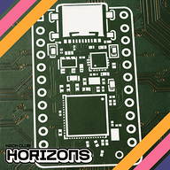
Routed PCB, Custom edge cut and Silkscreen
I routed all of the components together as neatly as I could, and created a flower design outline in Affinity Designer. I also created a custom silkscreen design that I think looks really cool. I used many vias in the PCB design to help work with the limited space available.
Next, I will set up the Git Repo and get ready to submit!


Silas
added to the journal ago
Schematic Completed
I know I don't have to journal for the LED chaser, but I have gotten used to it and enjoy the process. In the schematic, I wired up the main 555 timer board and the IO expander to the ten LEDs. I followed the 555 module datasheet for the correct way to make it in astable mode. Lastly, I added pads for power input on the board, and made the schematic look nice and organized with labels.

Silas
started LED Chaser ago
1/3/2026 6 PM - Schematic Completed
I know I don't have to journal for the LED chaser, but I have gotten used to it and enjoy the process. In the schematic, I wired up the main 555 timer board and the IO expander to the ten LEDs. I followed the 555 module datasheet for the correct way to make it in astable mode. Lastly, I added pads for power input on the board, and made the schematic look nice and organized with labels.
1/3/2026 7 PM - Routed PCB, Custom edge cut and Silkscreen
I routed all of the components together as neatly as I could, and created a flower design outline in Affinity Designer. I also created a custom silkscreen design that I think looks really cool. I used many vias in the PCB design to help work with the limited space available.
Next, I will set up the Git Repo and get ready to submit!
1/3/2026 8 PM - Fixed Footprints!
Okay, so I was able to find the actual correct footprints in KICAD for the variable resistor and the non-radial capacitor. I think all of my footprints are now correct!
1/22/2026 4 PM - Soldered on main components
This was an incredibly difficult process, as all of the components are different heights, so I had to come up with solutions on the go. The two ICs were very easy and I soldered them first in around 15 minutes. Then, I put on the capacitors and resistors, by using pens and pencils to balance the components so they would not stick out too far (although the non-polar capacitor is definitely sticking out lol).
Lastly, I soldered on the pin headers, which took the longest of any component. I think my iron is oxidizing, so this was even harder, and after I soldered them on unevenly, I flipped the PCB and heated it from the back side so that they would fall into place all the way (this worked surpisingly well after I figured it out!). I used this same method for the potentiometer, which probably took 15 minutes alone :sob:.
Also, my PCBs turned out super cool looking! Well worth the wait.
1/22/2026 6 PM - Soldered LEDs and Tested!
After a long time trying to solder on an LED, I gave up for a bit and took a break while doing some research. It seems like oxidation is definitely the issue, so I put on a different tip, and instantly it became super easy to solder! The LEDs were very finicky, but I found an incredibly sketchy method to get them fully in. First, I would solder them upside down slightly sticking out, and then push it in with my finger while heating it (this had the potential for disaster but I just did it super slowly and it worked out).
I was able to solder all of the (white) LEDs after quite some time. It was very difficult, but still doable! I plugged some wires into my PICAT devboard (:wink:) and the board and I was so relieved that it actually lit up! The potentiometer seems to work as well!