CCKB KEYB
i want to create a keyboard with a 75% keyboard layout, display , a knob and leds
Created by
 chris
chris
Tier 3
35 views
1 follower
 CAN ⚡🚀
approved CCKB KEYB ago
CAN ⚡🚀
approved CCKB KEYB ago
Tickets awarded: 165 tickets
Tier: 3
you have one super long entry so I have to deflate more.
chris
submitted CCKB KEYB for ship review ago
chris
added to the journal ago
finished the code
i have assembled it all, and most keys work alright, the case fits perfectly and i think the keyboard looks very good. I am quite happy with the result. It took me a while to assemble as i had to change the case as switches where to tight to fit. Also soldered the screen.

chris
added to the journal ago
new case
I have fully redesigned the case, now it looks quite good i think, and it is ALOT easier to print and assemble. the plate is part of the top case and the base is just the base.

chris
added to the journal ago
ALOT OF THINGS HAPPENED
Part 1
ok, so i finished soldering all the diodes about a week and a half ago, and started doing the leds. HOWEVER the leds were not working after the second ones, I tried fixing for about 30 minutes. But it ended in me breaking the pads while trying to desolder them.  . and so I decided to attempt to desolder the controller, which didnt work, and stupidly i then bought a mini hotplate to try desolder it, which of course didnt work, infact it broke the microcontroller :/

and therefore i just bought a new one(with my own money) and more diodes.
Part 2
While i am waiting for it to arrive, i decided to get a esp32 c3 mini microcontroller and connect 3 wires to it, 5v,gnd, and a pin to the ledinput.
I used this to test the leds while i was soldering, and ALL THE LEDS WORKED!!!!!(Made me happy :D) some of the grounds werent connected in pcb so i had to connect wires to them.


and then i soldered all the diodes and the hotswap sockets.

Then i cleaned it all which took about 30 minutes
Once the microcontroller arrives i will solder it(correctly hopefully) and code it :D
chris
added to the journal ago
Getting started
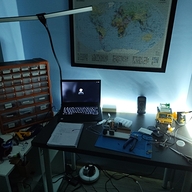
Today my PCB finally arrived after about 2 weeks, so now I have every part u need to get started soldering, I have begun soldering the sod-123 diodes, but it's taking a long time, already took 3h for half of the diodes, as I have never done soldering this small ever, and now my back also hurts. I also cleaned my desk so I can keep everything organised and printed the case frame.

CAN ⚡🚀
approved CCKB KEYB ago
Tier approved: 3
Grant approved: $103.00
Very nice and polished
chris
submitted CCKB KEYB for ship review ago
chris
added to the journal ago
rerouted leds once again
I had to re-wire leds once again as i did the wrong ones(sk6812 mini instead of mini-e), this leds were ALOT harder to route as they have a hole in the middle which means i cant put a wire in it.

I am now re-doing the BOM as i want to use pcba since i cant solder smd
chris
added to the journal ago
rerouted leds
I have spent about 2 hours rewiring all the leds as i used the wrong ones.

I also removed the gpio extender as it wasn't needed and moved the rotary encoder to the switch matrix 

I also changed the case a bit so the plate is the top part of the case.
now i need to change the leds again as i used wrong ones. :C
 zsharpminor ⚡
requested changes for CCKB KEYB ago
zsharpminor ⚡
requested changes for CCKB KEYB ago
Hi: is there a reason you're buying two sets of 100 switches? Please only buy what you need, and try to get the cheapest version possible. Additionally, please attach a full screenshot of your AliExpress cart and show your JLCPCB options. Finally, please make a top case for your project. Thanks!
chris
added to the journal ago
updated pcb
i have updated the pcb and added all the files to github again as i forgot to update then b4
 i dont think there is anything else to do so i pretty much finished :D
chris
added to the journal ago
re-routed pcb
i got some tips to remove the matrix from the mcp23017, so i rerouted everthing, now the mcp23018 is only for the rotary encoder, i have also added 3 resistors, 2 for i2c and 1 for the leds.
chris
submitted CCKB KEYB for ship review ago
chris
added to the journal ago
Finished everything
I finished the BOM and also created my github repo, i am quite happy with how it came out, hope it gets accepted so i can build, managed to make it sub 100

chris
added to the journal ago
FINISHED CASE
I have finally finished building my case, the usb c port thing is removable because sometimes i get measurements wrong and its cheaper to print a small part instead of big part

chris
added to the journal ago
started the case & BOM
I have almost finished the BOM 
I also started designing the case, and finished making the plate, this took a while because the switch measurements were weird.
chris
added to the journal ago
finished pcb
I have finally finished my pcb and i think it looks great, It has 1x rotary encoder, 1x 0.91 oled, about 78 keys, hotswap sockets, and uses a mcu23017 for gpio expander. i am going to do the case next.

Ik the mounting holes are random but thats where i had space :D
chris
added to the journal ago
routed matrix
I have finished wiring the keyboard matrix and leds, this was quite time consuming as i had to not get stuck haha

I found this way to wire the leds as they kept getting stuck

chris
added to the journal ago
started routing pcb
I have finished doing the pcb layout and i added the leds, rasberry pi pico and started adding diodes, I also decided to add a 0.91 inch oled display

 .
.
chris
added to the journal ago
keyboard matrix
I have chosen my microcontroller- rasberry pi pico. I have also made my keyboard matrix and added leds.

I will now make the layout using the keys, also added hotswap switches
 ramesharavind2010
gave kudos to CCKB KEYB ago
ramesharavind2010
gave kudos to CCKB KEYB ago
Hey i am intermediate follow me and good luck
chris
added to the journal ago
chose layout

I have made my keyboard layout, I decided to use a 75% layout as I like to have FN keys but while keeping it compact as I want more desk room, I think the layout came out great.
chris
added to the journal ago
doing reasearch
I have just started the project and i am currently doing reasearch on the components, since i am a beginner this part will take me a while
i have found a photo of keyboard units.

chris
started CCKB KEYB ago
1/21/2026 4:36 PM - doing reasearch
I have just started the project and i am currently doing reasearch on the components, since i am a beginner this part will take me a while
i have found a photo of keyboard units.
1/21/2026 4:54 PM - chose layout
I have made my keyboard layout, I decided to use a 75% layout as I like to have FN keys but while keeping it compact as I want more desk room, I think the layout came out great.
1/21/2026 8 PM - keyboard matrix
I have chosen my microcontroller- rasberry pi pico. I have also made my keyboard matrix and added leds.
I will now make the layout using the keys, also added hotswap switches
1/22/2026 - started routing pcb
I have finished doing the pcb layout and i added the leds, rasberry pi pico and started adding diodes, I also decided to add a 0.91 inch oled display
.
1/23/2026 5 PM - routed matrix
I have finished wiring the keyboard matrix and leds, this was quite time consuming as i had to not get stuck haha
I found this way to wire the leds as they kept getting stuck
1/23/2026 6 PM - finished pcb
I have finally finished my pcb and i think it looks great, It has 1x rotary encoder, 1x 0.91 oled, about 78 keys, hotswap sockets, and uses a mcu23017 for gpio expander. i am going to do the case next.
Ik the mounting holes are random but thats where i had space :D
1/24/2026 1 PM - started the case & BOM
I have almost finished the BOM
I also started designing the case, and finished making the plate, this took a while because the switch measurements were weird.
1/24/2026 4 PM - FINISHED CASE
I have finally finished building my case, the usb c port thing is removable because sometimes i get measurements wrong and its cheaper to print a small part instead of big part
1/24/2026 6 PM - Finished everything
I finished the BOM and also created my github repo, i am quite happy with how it came out, hope it gets accepted so i can build, managed to make it sub 100
1/25/2026 12 PM - re-routed pcb
i got some tips to remove the matrix from the mcp23017, so i rerouted everthing, now the mcp23018 is only for the rotary encoder, i have also added 3 resistors, 2 for i2c and 1 for the leds.
1/25/2026 2 PM - updated pcb
i have updated the pcb and added all the files to github again as i forgot to update then b4
i dont think there is anything else to do so i pretty much finished :D
2/15/2026 1 PM - rerouted leds
I have spent about 2 hours rewiring all the leds as i used the wrong ones.
I also removed the gpio extender as it wasn't needed and moved the rotary encoder to the switch matrix
I also changed the case a bit so the plate is the top part of the case.
now i need to change the leds again as i used wrong ones. :C
2/15/2026 3 PM - rerouted leds once again
I had to re-wire leds once again as i did the wrong ones(sk6812 mini instead of mini-e), this leds were ALOT harder to route as they have a hole in the middle which means i cant put a wire in it.
I am now re-doing the BOM as i want to use pcba since i cant solder smd
3/4/2026 - Getting started
Today my PCB finally arrived after about 2 weeks, so now I have every part u need to get started soldering, I have begun soldering the sod-123 diodes, but it's taking a long time, already took 3h for half of the diodes, as I have never done soldering this small ever, and now my back also hurts. I also cleaned my desk so I can keep everything organised and printed the case frame.
3/21/2026 - ALOT OF THINGS HAPPENED
Part 1
ok, so i finished soldering all the diodes about a week and a half ago, and started doing the leds. HOWEVER the leds were not working after the second ones, I tried fixing for about 30 minutes. But it ended in me breaking the pads while trying to desolder them. . and so I decided to attempt to desolder the controller, which didnt work, and stupidly i then bought a mini hotplate to try desolder it, which of course didnt work, infact it broke the microcontroller :/
and therefore i just bought a new one(with my own money) and more diodes.
Part 2
While i am waiting for it to arrive, i decided to get a esp32 c3 mini microcontroller and connect 3 wires to it, 5v,gnd, and a pin to the ledinput.
I used this to test the leds while i was soldering, and ALL THE LEDS WORKED!!!!!(Made me happy :D) some of the grounds werent connected in pcb so i had to connect wires to them.
and then i soldered all the diodes and the hotswap sockets.
Then i cleaned it all which took about 30 minutes
Once the microcontroller arrives i will solder it(correctly hopefully) and code it :D
3/23/2026 - new case
I have fully redesigned the case, now it looks quite good i think, and it is ALOT easier to print and assemble. the plate is part of the top case and the base is just the base.
3/29/2026 - finished the code
i have assembled it all, and most keys work alright, the case fits perfectly and i think the keyboard looks very good. I am quite happy with the result. It took me a while to assemble as i had to change the case as switches where to tight to fit. Also soldered the screen.