glamrock freddy teacher, for mit
Hello, this is my project to apply to MIT or get a scholarship at a university in my country. The idea is for the robot to serve as a teacher. I will write a narrative documentary covering topics such as biomechanics (inspiration for joints), mechanics (force multiplication mechanisms), and chemistry (the plastics used to make the robot's parts and casing).
Created by
 santiagocuenta112az
Tier 1
34 views
3 followers
 cubit010 ⚡
requested changes for glamrock freddy teacher, for mit ago
cubit010 ⚡
requested changes for glamrock freddy teacher, for mit ago
user request
transfer to stasis
Tier: 1
santiagocuenta112az
submitted glamrock freddy teacher, for mit for ship review ago
santiagocuenta112az
added to the journal ago
eyes
Thanks for following the project; I'm excited to know there are people interested in it. Regarding the updates, I replaced all the eye motors with MG90s and decided to make the eyes completely automatic and independent of the program I use to animate the robot. It's more difficult to animate eight motors than to use a pre-made animation in code for them to move. But I won't stop there. I'll integrate an 8GB Raspberry Pi 5 into the eyes so the movement looks more realistic and it can occasionally follow someone with its gaze, as well as record what the robot sees and answer children's questions.


 tap
gave kudos to glamrock freddy teacher, for mit ago
tap
gave kudos to glamrock freddy teacher, for mit ago
hope you get into every uni you apply cuz this shit is crazy
tap
gave kudos to glamrock freddy teacher, for mit ago
Yo dude i just wanna say, THIS PROJECT IS THE RADDEST THING IVE SEEN!!!!
santiagocuenta112az
added to the journal ago
finish te planetary gearbox
I finished modeling the planetary gearbox and added the servo motor. Now I need to plan how to attach the arm to the robot. I need to make a joint so the planetary gearbox can move up and down. I also need to buy more motors and transformers for the chest and arms.


I didn't take into account some tolerances of the model, so I had to sand the part where the servo motor goes so that it would fit.
santiagocuenta112az
added to the journal ago
arrangements
I finally decided to put the controller board outside the robot for better accessibility, and to make it look good I'll make it into a backpack with RGB lights and other things
https://lapse.hackclub.com/timelapse/ppF4q1_NnGs2

santiagocuenta112az
added to the journal ago
event
A week ago, I entered an Arduino Days 2026 event at a university in my country. Of all the projects submitted, they chose 5 for each category (university, school, open). I entered as one of the 5 participants for the school category and ended up winning 2nd place. For the event, my father helped me build a wooden base with a drainpipe that could withstand the robot's weight.
The day before the event we didn't sleep because we were putting the finishing touches on everything, but it was totally worth it :>

WhatsApp Video 2026-04-03 at 14.00.26
WhatsApp Video 2026-04-03 at 14.00.32WhatsApp Video 2026-04-03 at 14.00.34

I forgot to mention that my school made a video before the competition; I'll leave it here in case you want to see it.
https://www.instagram.com/reel/DWkRsWcDNN6/?utm_source=ig_web_copy_link&igsh=MzRlODBiNWFlZA==
santiagocuenta112az
added to the journal ago
Let's continue with the forearm
First, I started by designing the arm with some sticks that have a 60-tooth gear, and then I made another 30-tooth gear that connects to the DS3240 servo motor. Between sanding and filling to give it a good finish, it took me about 3 hours. (There are two forearms, so it took me about 6 hours in total.)


santiagocuenta112az
added to the journal ago
arm
For this part of the arm, I used the gyroid infill shape, as it can better cushion the load. I printed it horizontally so that the piece wouldn't break. I added two nuts with a soldering iron and a through bolt so that the forearm could be added later. (It took me 3 hours to sand the forearm and add the screws, as well as fill some areas with putty) (There are two arms, so it took 6 hours in total.)


santiagocuenta112az
added to the journal ago
building the planetary gearboxes
It takes me about 4 hours to give the final touches to each box so that it can be used correctly. This is because some screws were interrupting the gearing of the teeth because they were too close to the toothed part of the circular structure. Therefore, I cut them with a Dremel. Then I sanded part of the torque outlet because it was tightening too much at the edges due to not taking into account the tolerances of the material (I used PETG for the construction of the boxes).


santiagocuenta112az
added to the journal ago
the planetary gerarbox
Planetary gearboxes work by distributing torque across three different gears meshed around a central gear called the sun gear. The sun gear transmits the initial torque, and the planet gears distribute it. These three planet gears are mounted on a carrier consisting of rods that connect to the torque output. Recalling the laws of thermodynamics, whenever something is gained, something must be lost; no system is 100% efficient. Therefore, when we gain force (torque), we lose speed. In this case, we have a 3:1 planetary gearbox, which indicates three times the force, but the motor must rotate three times faster for the torque output to complete one full revolution. Fortunately, we're working with animatronics, and speed isn't a determining factor. After all, you don't move your arm very fast. The motors I'll use for this part will be DS3240s. After that, I started designing the planetary gearboxes in Fusion 360. 2026-01-30 17-29-41
What you see in the video is the preliminary design of the box; in the end, I modified it in Blender to enlarge it slightly and be able to insert some through screws.

santiagocuenta112az
added to the journal ago
Let's start with the arms
The arm weighs approximately 1.5 kilograms. The problem is that several factors must be considered to move it without straining the motor; that's where my calculations come in. First, I measured and weighed each part. Then, after a few hours of thinking, I arrived at the following formula: the sum of (m.g.l.). This is because the arm consists of three parts: the upper arm, forearm, and hand, each with its own weight, hence the mass factor. Then, the force of gravity acts on each part, so the gravity factor is added. Finally, it is multiplied by the length of the object since the weight can increase depending on the degree of inclination, in this case, I'm referring to the contraction of the forearm at the elbow joint. Using that formula, I calculated the torque that each motor should have, coming out to about 7.49 N/m. But I had only bought 4 N/m motors, so I decided to use a planetary gearbox to multiply the torque.


 CAN ⚡🚀
approved glamrock freddy teacher, for mit ago
CAN ⚡🚀
approved glamrock freddy teacher, for mit ago
Tickets awarded: 2850 tickets
Tier: 1
Awesome project!
santiagocuenta112az
added to the journal ago
support
For the support structure, I plan to use a metal piece that I'll have made on a lathe once I finish the plans. My father will help me with this part, as he's the one who needs to understand the plans to have the piece made, and I don't know anything about drawing. Therefore, my plans look more like something a 3-year-old would draw than a 16-year-old. Moving on to the important part, I have a tube in the middle, printed in carbon fiber-reinforced PLA, which contains a NEMA 17 stepper motor so the robot's chest can move from side to side.


In this case, the plans took about 57 minutes, but the design of the tube for the NEMA 17 motor took about 4 hours.
santiagocuenta112az
added to the journal ago
Pelvis
After that, I started printing the pelvis. It was separated into two parts, as it didn't fit in the printing chamber, and printed in ABS to give it maximum strength. Then it was joined with screws and industrial epoxy resin.


santiagocuenta112az
added to the journal ago
jaw
For the jaw, use a simpler system; it's just a stick connected to a part of the jaw that transmits the servomotor's movement to the jaw. Perhaps the only problem is that it moves too violently.


 . I modified them to add space for the camera, but the eye got stuck between the eyelids, so I enlarged them so that the eye could move correctly.


santiagocuenta112az
added to the journal ago
eyes 2.0
As I observed this, I decided to design my own eyes with space for a Raspberry Pi 2 camera, but they were too unstable and kept falling out of their sockets. Also, the material I used to print the eyes was too poor and broke too easily.

santiagocuenta112az
added to the journal ago
eyes
Then I started designing the eyes. I began with a first model I found online, but it was too small for the head. Then I decided to add cameras to the eyes to add artificial intelligence with a Raspberry Pi, but the model didn't have enough space, so I decided to change it.


santiagocuenta112az
added to the journal ago
clarification
The hours I list in each post include both model design and assembly. I don't include printing hours because I haven't tracked them. I measure my time by noting the start and end times of everything I do on the robot. There have been times when I haven't done this, so I use what I remember to give an estimate. All the hours listed are a cumulative total from different days. I dedicate at least 3 hours to the robot each day.
santiagocuenta112az
added to the journal ago
chest
The movement of the robot's plates uses a gear and a toothed rod that meshes to move the entire chest structure forward; the chest plate is connected to a servomotor that pushes it upwards


santiagocuenta112az
added to the journal ago
paint
After all that, I began to paint the parts of the robot with four different paints: a beige color for the chest plates, a madder orange for the body, and a frosted metallic blue for the details of the chest, jaw, and eyes.

santiagocuenta112az
added to the journal ago
the neck
For the neck, use two MG995 servomotors connected to a screw that is attached to two points on the neck to allow the head to tilt to the sides. Then synchronize the servos so that when one moves to one side, the other moves to the opposite side, thus achieving movement without straining either servo.


santiagocuenta112az
added to the journal ago
neck
For the central part of the robot, use PETG. In the middle, there is a motor that moves the head to the sides. It has a space to place a bearing embedded in a tube, thus giving it better stability.

CAN ⚡🚀
submitted glamrock freddy teacher, for mit for ship review ago
santiagocuenta112az
added to the journal ago
waist
After that I started printing the waist parts, repeating the process but this time leaving slightly higher tolerances so the material wouldn't break when working with it. Something I forgot to mention in the previous post is that I applied automotive filler to the joints of the pieces to make them uniform.cintura 2
cinture

santiagocuenta112az
added to the journal ago
construction begins!
I started by building the upper chest and head, joining them with 3D printed rectangular sticks. I took the design of the shell from an image of the character found online (you can see the exact quote in the repository). This stage of construction was especially difficult because I didn't have much experience with it and I kept breaking pieces, but I managed it. In these videos, you can see the pieces joined together and the unpainted robot. (https://www.youtube.com/watch?v=w9MqOOe3WEY) (https://www.youtube.com/watch?v=ANeyHq2PXxs)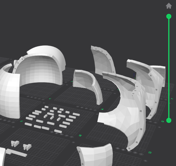cabeza-convertedcarcasa-convertedmandibula
ojoparte mid face 2parte mid faceparte pecho 6parte pecho 4parte pecho 5
parte pecho
parte pecho 2
santiagocuenta112az
submitted glamrock freddy teacher, for mit for ship review ago
santiagocuenta112az
added to the journal ago
inspiration
During the planning period, there was a teacher who always talked to us about aiming higher, studying abroad, and so on, since education in my country isn't the best. So one night, while having dinner with my father, I told him about my idea to create the robot to apply to MIT. My father supported the idea and told me he would enroll me in English classes the following year so I could apply. I told my geography teacher, the one who had initially inspired me, about the robot and asked him about presenting it, since I wanted to inspire others with my creation. He said he could get me a classroom once the robot was finished so I could show my project to the younger students. (Here's a message from the teacher that I'll use in the documentary.)

santiagocuenta112az
added to the journal ago
3d printer
At the end of the third term of my fourth year of high school, my father bought me my 3D printer, a Creality K1C. I got a final average of 16.4. I started doing tests to learn about the printer. During this stage, I printed several things, nothing too interesting. Total accumulated hours: 90
santiagocuenta112az
added to the journal ago
3d modeling
After that I started developing the first versions of the robot's 3D model. In total, I spent 56 hours modeling, accumulated over the months I spent improving the mechanisms. Up until that point, I didn't have the printer, so I couldn't start printing the parts.


santiagocuenta112az
added to the journal ago
expanding horizons
After having the idea in my head for a while, I got out of bed and said I would make the robot, and I started planning the idea. I told my father about it and he said he would buy me a 3D printer if I got good grades, so I started drawing my ideas during class and watched Blender videos to learn how to design in 3D (in total drawing ideas and learning Blender I spent about 47 hours, 13 hours drawing and 24 learning the basics, these are hours accumulated during the weeks that this stage lasted)


santiagocuenta112az
added to the journal ago
previous context
During my childhood, I was fascinated by technology and outer space. I remember once my father took my brother and me to a planetarium; it was an incredible experience. Despite that, I never considered creating anything myself because it seemed too difficult. Years passed, and I started at a new school. There, I had a radical change in mindset and began to take risks. While in a computer class where we had to create a blog about a topic of our choice, I decided to research NASA rovers. Then I began to design my own rover. (esto lo hice durante unas 2 semanas) When I told my parents about the idea, they s

upported me and encouraged me to create it.
santiagocuenta112az
added to the journal ago
project explanation
I will begin to tell you all the important things about the construction of the robot, following a small timeline. In each post, I will add detailed explanations of everything I did and the context of the moment.

santiagocuenta112az
started glamrock freddy teacher, for mit ago
2/24/2026 5 PM - project explanation
I will begin to tell you all the important things about the construction of the robot, following a small timeline. In each post, I will add detailed explanations of everything I did and the context of the moment.
2/24/2026 6:09 PM - previous context
During my childhood, I was fascinated by technology and outer space. I remember once my father took my brother and me to a planetarium; it was an incredible experience. Despite that, I never considered creating anything myself because it seemed too difficult. Years passed, and I started at a new school. There, I had a radical change in mindset and began to take risks. While in a computer class where we had to create a blog about a topic of our choice, I decided to research NASA rovers. Then I began to design my own rover. (esto lo hice durante unas 2 semanas) When I told my parents about the idea, they s
upported me and encouraged me to create it.
2/24/2026 6:33 PM - expanding horizons
After having the idea in my head for a while, I got out of bed and said I would make the robot, and I started planning the idea. I told my father about it and he said he would buy me a 3D printer if I got good grades, so I started drawing my ideas during class and watched Blender videos to learn how to design in 3D (in total drawing ideas and learning Blender I spent about 47 hours, 13 hours drawing and 24 learning the basics, these are hours accumulated during the weeks that this stage lasted)
2/24/2026 6:55 PM - 3d modeling
After that I started developing the first versions of the robot's 3D model. In total, I spent 56 hours modeling, accumulated over the months I spent improving the mechanisms. Up until that point, I didn't have the printer, so I couldn't start printing the parts.
2/24/2026 7 PM - 3d printer
At the end of the third term of my fourth year of high school, my father bought me my 3D printer, a Creality K1C. I got a final average of 16.4. I started doing tests to learn about the printer. During this stage, I printed several things, nothing too interesting. Total accumulated hours: 90
1762560860
17657177492025-09-25 15-13-37
1762560860

2/24/2026 8 PM - inspiration
During the planning period, there was a teacher who always talked to us about aiming higher, studying abroad, and so on, since education in my country isn't the best. So one night, while having dinner with my father, I told him about my idea to create the robot to apply to MIT. My father supported the idea and told me he would enroll me in English classes the following year so I could apply. I told my geography teacher, the one who had initially inspired me, about the robot and asked him about presenting it, since I wanted to inspire others with my creation. He said he could get me a classroom once the robot was finished so I could show my project to the younger students. (Here's a message from the teacher that I'll use in the documentary.)
3/22/2026 10:38 PM - construction begins!
I started by building the upper chest and head, joining them with 3D printed rectangular sticks. I took the design of the shell from an image of the character found online (you can see the exact quote in the repository). This stage of construction was especially difficult because I didn't have much experience with it and I kept breaking pieces, but I managed it. In these videos, you can see the pieces joined together and the unpainted robot. (https://www.youtube.com/watch?v=w9MqOOe3WEY) (https://www.youtube.com/watch?v=ANeyHq2PXxs)[cabeza-converted](/user-attachments/blobs/proxy/eyJfcmFpbHMiOnsiZGF0YSI6MTI1OTU1LCJwdXIiOiJibG9iX2lkIn19--99ea5e9d7374f81b9c5e397bc331082c749fea1e/cabeza-converted.mp4)[carcasa-converted](/user-attachments/blobs/proxy/eyJfcmFpbHMiOnsiZGF0YSI6MTI1OTU2LCJwdXIiOiJibG9iX2lkIn19--d1328fac03bf851cd3e8707abd7766afda7865a1/carcasa-converted.mp4)[mandibula](/user-attachments/blobs/proxy/eyJfcmFpbHMiOnsiZGF0YSI6MTI1OTU3LCJwdXIiOiJibG9iX2lkIn19--434f3d0fb3307a128ff6337c8d096af649944873/mandibula.mp4)
ojoparte mid face 2parte mid faceparte pecho 6parte pecho 4parte pecho 5
parte pecho
parte pecho 2
3/22/2026 10:47 PM - waist
After that I started printing the waist parts, repeating the process but this time leaving slightly higher tolerances so the material wouldn't break when working with it. Something I forgot to mention in the previous post is that I applied automotive filler to the joints of the pieces to make them uniform.cintura 2
cinture
3/30/2026 4:19 PM - neck
For the central part of the robot, use PETG. In the middle, there is a motor that moves the head to the sides. It has a space to place a bearing embedded in a tube, thus giving it better stability.
3/30/2026 4:27 PM - the neck
For the neck, use two MG995 servomotors connected to a screw that is attached to two points on the neck to allow the head to tilt to the sides. Then synchronize the servos so that when one moves to one side, the other moves to the opposite side, thus achieving movement without straining either servo.
3/30/2026 4:33 PM - paint
After all that, I began to paint the parts of the robot with four different paints: a beige color for the chest plates, a madder orange for the body, and a frosted metallic blue for the details of the chest, jaw, and eyes.
3/30/2026 4:37 PM - chest
The movement of the robot's plates uses a gear and a toothed rod that meshes to move the entire chest structure forward; the chest plate is connected to a servomotor that pushes it upwards
3/30/2026 4:52 PM - clarification
The hours I list in each post include both model design and assembly. I don't include printing hours because I haven't tracked them. I measure my time by noting the start and end times of everything I do on the robot. There have been times when I haven't done this, so I use what I remember to give an estimate. All the hours listed are a cumulative total from different days. I dedicate at least 3 hours to the robot each day.
3/30/2026 5:20 PM - eyes
Then I started designing the eyes. I began with a first model I found online, but it was too small for the head. Then I decided to add cameras to the eyes to add artificial intelligence with a Raspberry Pi, but the model didn't have enough space, so I decided to change it.
3/30/2026 5:24 PM - eyes 2.0
As I observed this, I decided to design my own eyes with space for a Raspberry Pi 2 camera, but they were too unstable and kept falling out of their sockets. Also, the material I used to print the eyes was too poor and broke too easily.
3/30/2026 5:28 PM - Eyes 3.0 final final now definitive
To conclude with the eyes, I used a model from the internet, this one in question (https://www.printables.com/model/1435865-46mm-animatronic-single-eye-four-servo-design). I modified them to add space for the camera, but the eye got stuck between the eyelids, so I enlarged them so that the eye could move correctly.
3/30/2026 5:36 PM - jaw
For the jaw, use a simpler system; it's just a stick connected to a part of the jaw that transmits the servomotor's movement to the jaw. Perhaps the only problem is that it moves too violently.
. This is because the arm consists of three parts: the upper arm, forearm, and hand, each with its own weight, hence the mass factor. Then, the force of gravity acts on each part, so the gravity factor is added. Finally, it is multiplied by the length of the object since the weight can increase depending on the degree of inclination, in this case, I'm referring to the contraction of the forearm at the elbow joint. Using that formula, I calculated the torque that each motor should have, coming out to about 7.49 N/m. But I had only bought 4 N/m motors, so I decided to use a planetary gearbox to multiply the torque.
4/1/2026 9:01 PM - the planetary gerarbox
Planetary gearboxes work by distributing torque across three different gears meshed around a central gear called the sun gear. The sun gear transmits the initial torque, and the planet gears distribute it. These three planet gears are mounted on a carrier consisting of rods that connect to the torque output. Recalling the laws of thermodynamics, whenever something is gained, something must be lost; no system is 100% efficient. Therefore, when we gain force (torque), we lose speed. In this case, we have a 3:1 planetary gearbox, which indicates three times the force, but the motor must rotate three times faster for the torque output to complete one full revolution. Fortunately, we're working with animatronics, and speed isn't a determining factor. After all, you don't move your arm very fast. The motors I'll use for this part will be DS3240s. After that, I started designing the planetary gearboxes in Fusion 360. 2026-01-30 17-29-41
What you see in the video is the preliminary design of the box; in the end, I modified it in Blender to enlarge it slightly and be able to insert some through screws.
4/1/2026 9:07 PM - building the planetary gearboxes
It takes me about 4 hours to give the final touches to each box so that it can be used correctly. This is because some screws were interrupting the gearing of the teeth because they were too close to the toothed part of the circular structure. Therefore, I cut them with a Dremel. Then I sanded part of the torque outlet because it was tightening too much at the edges due to not taking into account the tolerances of the material (I used PETG for the construction of the boxes).
4/2/2026 12 AM - arm
For this part of the arm, I used the gyroid infill shape, as it can better cushion the load. I printed it horizontally so that the piece wouldn't break. I added two nuts with a soldering iron and a through bolt so that the forearm could be added later. (It took me 3 hours to sand the forearm and add the screws, as well as fill some areas with putty) (There are two arms, so it took 6 hours in total.)
4/2/2026 1 PM - Let's continue with the forearm
First, I started by designing the arm with some sticks that have a 60-tooth gear, and then I made another 30-tooth gear that connects to the DS3240 servo motor. Between sanding and filling to give it a good finish, it took me about 3 hours. (There are two forearms, so it took me about 6 hours in total.)
4/3/2026 8:33 PM - event
A week ago, I entered an Arduino Days 2026 event at a university in my country. Of all the projects submitted, they chose 5 for each category (university, school, open). I entered as one of the 5 participants for the school category and ended up winning 2nd place. For the event, my father helped me build a wooden base with a drainpipe that could withstand the robot's weight.
The day before the event we didn't sleep because we were putting the finishing touches on everything, but it was totally worth it :>
WhatsApp Video 2026-04-03 at 14.00.26
WhatsApp Video 2026-04-03 at 14.00.32WhatsApp Video 2026-04-03 at 14.00.34
I forgot to mention that my school made a video before the competition; I'll leave it here in case you want to see it.
https://www.instagram.com/reel/DWkRsWcDNN6/?utm_source=ig_web_copy_link&igsh=MzRlODBiNWFlZA==
4/3/2026 8:42 PM - arrangements
I finally decided to put the controller board outside the robot for better accessibility, and to make it look good I'll make it into a backpack with RGB lights and other things
https://lapse.hackclub.com/timelapse/ppF4q1_NnGs2
4/3/2026 8:54 PM - finish te planetary gearbox
I finished modeling the planetary gearbox and added the servo motor. Now I need to plan how to attach the arm to the robot. I need to make a joint so the planetary gearbox can move up and down. I also need to buy more motors and transformers for the chest and arms.
I didn't take into account some tolerances of the model, so I had to sand the part where the servo motor goes so that it would fit.
https://lapse.hackclub.com/timelapse/eWFto0wnufI4
4/5/2026 - eyes
Thanks for following the project; I'm excited to know there are people interested in it. Regarding the updates, I replaced all the eye motors with MG90s and decided to make the eyes completely automatic and independent of the program I use to animate the robot. It's more difficult to animate eight motors than to use a pre-made animation in code for them to move. But I won't stop there. I'll integrate an 8GB Raspberry Pi 5 into the eyes so the movement looks more realistic and it can occasionally follow someone with its gaze, as well as record what the robot sees and answer children's questions.