TARS Quote
A miniature TARS with an OLED display that shows text that is sent to it.
Created by
 Padimo
Tier 2
189 views
1 follower
 vmshade
gave kudos to TARS Quote ago
vmshade
gave kudos to TARS Quote ago
"They didn't bring us here to bring us here to change the past"
 CAN ⚡🚀
approved TARS Quote ago
CAN ⚡🚀
approved TARS Quote ago
Tier approved: 2
Grant approved: $103.00
Nice project
Padimo
submitted TARS Quote for ship review ago
Padimo
added to the journal ago
Add assembled image with components
This requires a lot of CAD as I don't actually have said image. So, here are all the things I'll need to add:
- Servos
- Move legs
- Add cutout for button (d-pad)
First of all, the d pad has no cad model that I could find. So, I'm going to make that (not too specifically though, its super complex). Then I'll download a servo model and implement it.
So, that's exactly what I did!

 zsharpminor ⚡
requested changes for TARS Quote ago
zsharpminor ⚡
requested changes for TARS Quote ago
Hi, you didn't follow the last feedback; I see no assembled image with components in your README.
Padimo
submitted TARS Quote for ship review ago
 Tanuki ⚡🚀
requested changes for TARS Quote ago
Tanuki ⚡🚀
requested changes for TARS Quote ago
Hey! This looks really intereesting, please include the full assembly CAD images in the readme though! THis seems like a nice gift :D
Padimo
added to the journal ago
Update previous post
Accidentally doubled the amazon cost in BOM, fixed it to be single counted again. The new cost is $91.88 which is faaaaar better than the 152 that it was previously.

Padimo
submitted TARS Quote for ship review ago
Padimo
added to the journal ago
Update prices
Turns out, Waveshare only has suuuper expensive shipping options... so I found the part on amazon at the following link: https://www.amazon.com/gp/product/B0BFQF8GT3
Total price now is $152.

Padimo
added to the journal ago
Fix changes
Added a schematic (see schematic.pdf).
I also added the ESP32 OTA example so that I have a base framework to start with once I get started on my project.

Padimo
added to the journal ago
Fix PCB, update BOM and Readme
BOM: added heat inserts. Switched to Amazon to reduce price (cost from adafruit > additional cost from Amazon). The display is different from Amazon to Waveshare so I switched the display back to Waveshare.
Readme: added descriptions of hardware and more detailed descriptions of planned software.
PCB: realized that the switch is supposed to be diagonal so I rotated it by 45º and rerouted the board.

 PenguinMo
requested changes for TARS Quote ago
PenguinMo
requested changes for TARS Quote ago
you need some firmware and also could you make a scematic and upload it if your not using a PCB
Padimo
submitted TARS Quote for ship review ago
Padimo
added to the journal ago
Fix mousebites
After receiving feedback in #electronics I'm switching my own mouse bites to the Panelization library's mouse bites by madworm.
I removed the pads I had placed before and adjusted the boards to be exactly 2mm apart, then added the 2mm mouse bites.


It uses layers I'm not familiar with, so let's break it down:

Here, we're looking at the smallest one. The yellow semicircles are silkscreen, so we can hide those for now. The small grey circles in the larger one are on the layer User.drawings, to provide the center of the large circles so that the edge.cuts can be drawn as such. These large circles are references, drawn on User.eco1 which has no set purpose. The small blue circles are drill holes, and aren't a specific layer, but they match the color of the mounting holes in the official library. Cool!
Padimo
added to the journal ago
BOM
Wrote BOM in Excel.
I updated my repo because I had neglected to do that previously. You should now be able to see my changes!
The journal is still empty on the repo for reasons I don't understand — if you're reading this on Blueprint then you're fine but nobody on github will see.
Clarifications: Notice I never wrote for the WS2812B. I will be using the strip and lining the inside of the robot with these, so no PCB/footprint is needed other than the header.

Padimo
added to the journal ago
Mounting Holes and Mouse Bites

They got back to me very quickly! M3 incoming
I first added mouse bites:

I aligned the boards to the grid (took forever), then drew 180º arcs. Between these arcs I added 1.0mm pads which have drilled holes. This was copy pasted four times to make the mouse bites. I then redrew edge.cuts.
I don't have space for the PCB to have M3. Also, the D pad needs to be very close to the surface, so adding heat inserts will hurt that distance. I need another way to mount this PCB.
I added the mounting holes for the display:

For mounting the PCB, I added these little tabs. The PCB fills the inside of the model fully so these are for vertical alignment.

Padimo
added to the journal ago
CAD update
Created PCB step and exported to Fusion, created a basic shell around it. I want the shell to magnetically pop off (or maybe unscrew, don't fully know yet) so there's no back yet. I also found a pretty big issue: the LED board and display overlap, which is bad. So I shortened the LED board and added a spacer so they don't quite overlap, and now it works out physically.
Also added the TARS ridge detail to the sides of the main body.
In terms of component placement (such as servos and speaker), I'll determine the best placement for those once components are received. This is to ensure that I don't need to worry about routing wires super precisely yet. Also, the WS2812Bs, in retrospect, don't really have a spot, so maybe I will need a strip of these and cut + paste them (ctrl x + v irl).
It also occurs to me that I don't want things moving around inside, so I need to add screws with heat inserts. Waveshare has terrible hardware documentation so I had to send in a support ticket asking what size their mounting holes were. For consistency, I'll use that same size for the rest of the PCBs, and I need to mount every single one with at least two screws, so I'll add those mounting holes next post.
Last things I did here were create cutouts in the body for the LED board LEDs so that the board could sit flush with the body instead of resting on top of it. You may realize that screws won't work because of the thinness of the shell and needing LEDs to be as close to the surface as possible. For this specific PCB I will glue it down, first with hot glue then with superglue. (Hot glue to hold it in place long enough for superglue to dry).


Note about those pins sticking up: they won't be there at all, I just had them there so that I could have mounting holes to wire to. The generated CAD just included them.
Action items for next post:
- PCB breakaway system
- back shell (screws or magnets)
- cutout for D pad
- mounting holes/heat insert sizing
Padimo
added to the journal ago
Routed the PCB
I just connected a bunch of stuff and if they got in the way I moved it. I don't really know how else to explain it, so I'll attach images of various nets.


And here's a 3D view:

I locked in super hard so there isn't much else to say. I rearranged some stuff very slightly.
In terms of the edge cuts from the last post, I uploaded to JLC to see what they would do, and here's what I found:
they glue it together, so I'll just add a breakaway next time.
Padimo
added to the journal ago
Rearranged PCB
Now that I've redesigned the schematic, I'll need to rearrange the PCB. Here are some key things I'm doing:
Minimizing space usage on the main board, compressing it to 34mm by 75mm. The USB-C breakout will be moved to the side of the board. And the LEDs for the Braille will also become a separate board.
The LEDs were placed according to the Braille on the Fusion CAD, and then I reassigned which LEDs were for each charlieplexed pin. I routed these. And, I routed the USB-C breakout. These were fairly easy and neither required any planes.
I switched ESP32S3 from having its antenna on the right side to on the left side, since previously the components on the top of the board were on the bottom of the ESP and vice versa. This required me to shift other stuff around.
I also wanted to modify edge.cuts to have mouse bites or something to make it easy to break away, but it looks like that might be a lot more work so first I want to see how JLC process it. So, I'll route the board first.
(Forgot to finish this before routing so the image is of the routed board)

Padimo
added to the journal ago
Editing Schematic
I removed the entirety of the capacitive touch stuff to replace with the newly created D pad, so I was able to replace 8 capacitive touch pads with five physical inputs. Great! Now I have three extra pins for whatever I want. I'll probably leave them disconnected. This also means I have way more space on the PCB. One thing I want to do, as I've mentioned before, is have the Braille TARS letters light up. Previously, I had planned to use charlieplexing to get a pattern for this Braille so I can animate it, and I was using three pins for a maximum of 6 distinct LEDs (multiple LEDs on same path). Now that I have three more pins, I can have 30 distinct LEDs. I only need 12 LEDs so I can use four wires. As I code this, I'll probably have to dedicate a separate task for the charlieplexing.
Here's the final schematic:

Padimo
added to the journal ago
Modifying components
In the last entry, I said that I would switch to physical switches from capacitive touch pads. This post is me doing that.
First of all, I found a really nice SparkFun D-pad and I think this is a really nice input device. Unfortunately there's no footprint that I could find online so I'll have to make one using the datasheet. Fortunately they just give it to you, so I'll just copy that over into the footprint editor.


Easy peasy!
Padimo
added to the journal ago
PCB arrangement
Annotation
All pin headers dealt with.
Horizontal:
- Servos
- Main board USB receptacle
- Display header Vertical:
- Cap touch (will be fills anyway)
- WS2812B (to avoid confusion with servos)
- I2C and SPI headers
- Speaker header
- USB receptacle board plug
PCB
Start with the dimensions. Another project reminded me to have tolerance so I'll do 3mm on each edge.
Since a large portion of the PCB needs to be dedicated to capacitive touch pads, I will need to make the rest of the PCB super dense.
I very quickly ran into an issue: the way I designed the USB receptacle interferes with the positioning of the capacitive touch pads, so I'll move the position ones up above the directional ones. I'm also thinking to switch to buttons, so we'll leave plenty of space for the touch pads where I may switch to buttons.
In terms of buttons, I'll probably use a 5 way switch or similar — that decision will be made in the future.
Another issue — I had wanted to put the LEDs right under where the Braille dots will be in the model, but there are several headers that need to go there and can't really be avoided. To rectify this I made them all vertical headers instead of horizontal, freeing space. I still don't know where to put the LEDs, but here's the current state of the PCB:

I'll move to making a physical switch and adjusting where the LEDs will go in the next entry, and perhaps start routing.
Padimo
added to the journal ago
Rebuild Schematic
I accidentally deleted my KiCad so I'm using previous journal entries to rebuild. This journal entry is effectively the backup with all pin connections for the ESP32 since I had a pretty nice layout before and want to recreate it.
I restructured a few things in the reconstruction:
- Capacitive touch pins are now each connected to their own conn01x01 instead of a large conn01x08. This is to customize the shape more precisely of each cap touch pad.
ESP32S3:
D+ from USBC D+
D- from USBC D-
EN from RESET
IO0 from BOOT
IO47 from SERV1
IO48 from SERV2
IO1 from UP
IO2 from DOWN
IO3 from LEFT
IO4 from RIGHT
IO5 from POS0
IO6 from POS1
IO7 from POS2
IO8 from POS3
IO10 from CS0
IO11 from MOSI
IO12 from SCK
IO13 from MISO
IO9 from WS2812B
IO14 from DIN
IO15 from BCLK
IO16 from FCLK
IO17 from SDMODE
IO46 from CS1
IO45 from CS2
IO42 from SDA
IO41 from SCL
In my previous entry I said I had very few pins left... but I have two pins available more than what I had last time. What am I missing?
In wiring the charlieplexing for the LEDs, I used up all but two pins (outside of PSRAM). Not bad!

Padimo
added to the journal ago
CAD 2 (Schematic)
Building from the previous one.
First I connected all the labels that hadn't previously been connected. Capacitive touch pads to the ESP channels, servos to open I/O pins, SPI display.
TBD:
- 3.3V regulator: AP2112K-3.3TRG1
- Audio circuitry
- I2C and SPI expansion ports (two of each)
First voltage regulator done (used previous design schematic). Now audio circuitry.
Since this section is effectively a speaker, I just found some projects that were ESP32 bluetooth speakers. Looks like the MAX98357A is perfect for amplification, and I'll use an 8Ω 3W speaker (2 pin header on schematic). As any good PCB designer does, I used the datasheet typical application circuit to make it. Hopefully my application is the "typical application" but I can't be bothered to check whether it actually is.

Looks like it's QFN. This means I'll need PCBA from JLC, or I'll need to find someone who is capable of QFN soldering. Or... I can learn it. Not a problem for current me.
After all is said and done... I only have IO16 and IO21 left and the only pin I've allocated for LEDs so far is IO9 for the WS2812Bs. That leaves me with 16 LEDs driven by two pins (five, if I use the PSRAM 35-37 and drop octal RAM, which I may).
I'm hesitant to use charlieplexing because it requires
Charlieplexing 16 LEDs requires...conveniently...five pins. Charlieplexing 8 LEDs for just the indicators requires four pins so I may as well use five.
Going back to the capacitive touch pads... I don't want their field to be interrupted so I need to check whether the LEDs will affect it.
Because I'll be charlieplexing them, they will be. So I need a new solution.
Update: I have lost my KiCad files for this project... I was clearing storage for my laptop and it's all missing. I'll try to quickly do this part again based on what I've documented here.
Padimo
added to the journal ago
More CAD (A)
First I measured how much space I'll have for a PCB. I don't want it to take up too much space because I want to include WS2812B LEDs throughout the inside of the robot. (I have yet to figure out how to route them to the outer legs, where they'll be or what they'll even do.)
I have $44-2(4)=36mm$ max width.
I'll limit the length to half of the available space, so $(176-2(4))/2=84mm$ max length.
I have 44/2-2(4)=14mm vertical height. This isn't as important to the PCB which will be 1.6mm thick, and I doubt other components will exceed an additional 5mm of height. The bulk of this space will likely be wiring.
I also want to set each of the Braille dots in the main body to be illuminated. Since they're 2.5mm in diameter and WS2812B are 5mmx5mm I'll probably just use 0805 LEDs.
Why PCB? Because I'm using ESP32S3-WROOM-1. I don't want to deal with a dev board.
Hmm. Genius idea: add two I2C and two SPI expansion ports on the back just for fun.
Components to be on the PCB:
- ESP32S3-WROOM-1
- all power management circuitry
- Headers
- Servo headers (x2 not x4)
- Display headers
- Speaker headers (yes I will include a speaker)
- MEMS microphone? if I end up including it. I'll leave space for it for sure.
While thinking (dangerous, I know) I have decided that the PCB is the MIDDLE half of the main body! Makes it easy, I can just put all headers at the top, and the OLED won't be pressed up against the PCB.
More thinking: I need inputs. Silly me! The ESP32 has built in capacitive touch channels so all I need to do are break these out (probably on the bottom).
Even more thinking: no need for servo lift mechanism because I don't want it to walk around if its tethered by a power cable anyway.
Note: try to avoid QFN, BGA, etc. anything super difficult to solder with just a hot plate and no pick and place machine
Here's the input layout I came up with:

The wide panel with arrows: the top middle will be up, bottom middle is down, left left, right right.
The stuff under: various positions the TARS can be in. The first one is just upright, the second one is leaning forward, the third one is one arm forward one back (probably I'll set which arm to be RNG) and the last one is to toggle sleep mode. Obviously on the actual model I can make it 3D so it will make more sense.
For these inputs I should add indicator LEDs. These will all be the same color as the Braille LEDs, and I'm thinking blue.
Didn't I say the PCB won't extend that far, you may ask? Yes, I did. And I changed my mind again. Now, the PCB will be three-quarters of the available space, so $176*3/4-4=128mm$ length.
Time to get to PCB design!
PCB design
First I add the ESP32 S3 and two servos. Then, an 8 pin header for the display. This is followed by the 16 LEDs. 8 capacitive touch inputs are also added (as a pin header). Three pins in a header are for WS2812B LEDs which will be added more specifically later on. These require 5V, so next I'll add some power management.
I wonder if USB-C might be the best option for this project. That way there's only one input anyway. I'll use the GCT_USB4085, since that's THT and therefore will have a strong physical connection. The orientation of the board forces the port to be at the bottom, but I want it at the back, so I'll design a slim breakaway board (first time!). This breakaway will have to be SUPER compact (14mm max, estimated 6mm from board, gives 8mm which is exactly the length of the breakaway; may need to rethink the PCB orientation) and have screw holes (means heat inserts in the 3D print point and a removable back panel (magnetic???)).
Rethinking PCB orientation: I want the PCB to be flush with the front of the robot. But the LED indicators and capacitive touch panels need to be in the front, so the CAD will need cutouts for those. This gives me about 10mm for the USBC breakaway which is much more comfortable.
^ these notes will be important considerations while drawing and routing the PCB. remember this is me thinking during schematics.
Padimo
added to the journal ago
Schematic design + CAD
Schematic design:
Components
- ESP32 WROOM
- 0.95" SSD1331 OLED
- 4x servo
- Neopixel LEDs
- SD card + reader
- Power management + power input port (I wanted battery but I don't think it'll work out)

To Do:
- Import SSD1331 into KiCad
- Servo calculations (are 9g ones strong enough)
- Neopixel patterns
- SD card reader location and storage needed
- Power management system
- Power input (5-12V adapter from wall outlet, at least 2m length)
- 5V regulator
- 3.3V regulator
- Logic level shifters 3.3V -> 5V (for 9g servos)
Servo calculations
Two of the servos will be rotating the outer legs; the other two will lift/lower legs enabling it to move effectively.
This means I have to design the lift mechanism so that I can do the calculations...
Servo Lift Mechanism
Paused.
Padimo
added to the journal ago
More Brainstorming
Needed to document research/ideation.
Components and Features
Features
- Concretely:
- Show whatever text is in the Firebase on the display
- Move legs (walking)
- LED highlights (that's my specialty)
- Memory to make a "log" (more on that later)
- Show images from SD
- Enable/disable name of whoever sent the text to the display (typically me, but could also be siblings and other friends etc.)
- some personality, showing time and weather i suppose
- Maybe (if time permits):
- Speech/conversations
Components
- ESP32 (preferably WROOM and not making everything myself, even though WROOM is probably more expensive for JLC SMT)
- 0.95" SSD1331 OLED
- 4x servo
- Neopixel LEDs
- SD card + reader
- Microphone/speakers?
- Power management + power input port (I wanted battery but I don't think it'll work out)
OLED I'm using:

Padimo
added to the journal ago
CAD
I normally start with the PCB but for this project I think it makes more sense for me to fit the PCB to the case (TARS not CASE) which means that I have to actually make the PCB.
CAD
The drawing I started with was the entire top face but I actually need to separate it... so I have to split sketch or something.
I started with the central piece, but then realized that the OLED I planned to use (0.95" SSD1331) is too big for what I'd drawn before. There's a really nice model of the robots here: https://www.thingiverse.com/thing:5156908
So I used these dimensions to start (22x176x22mm).
For the TARS lettering I found the font they used in the movie (Trade Gothic LT Std) and installed that.
Here's the top face (center only)

Took me an hour to discover circular pattern + combine intersect for the side piece. Thank goodness I can rectangular pattern it to make the second one.

Finished CAD for now. Will add arm servos for the side pieces later, and will fill in the rest of the central portion once a PCB and other electronics have been added.
Padimo
added to the journal ago
Brainstorm + Drawing
TARS Quote
A heartfelt communication device based on the robot TARS from Interstellar
This has been a vague idea brewing for a while, so first I brainstormed:
Features
- Show quote
- From multiple people
- Tracked with Firebase? I've used it before with ESP32 so should be straightforward
- Requires: ESP32, 0.96" OLED
- Scroll if longer quotes
- Requires: EC11 rotary encoder (with button because why not)
- Change position or walk
- needs servos
Cool features that I might want to add (based on GPTARS):
- moving each of the four segments individually
- speaker so it can talk
- or microphone and speaker combo to make it walkie-talkie (but over WiFi)
- lights because LEDs make everything cooler
Other software features
- Auto dim at night
- Display on/off switch (will reset in the morning)
- LED patterns
I don't want to make it too complicated (yet) so that's all the features for now.
Added features to readme.
Made rough CAD drawings (2D) of the top face in Fusion, with dimensions. It occurs to me that if I want this thing to walk or at least have motors in the joints that actually do something, then I'll need some translational motion at least on the outer legs. That kind of assembly will be added because I want it to be able to walk
Padimo
started TARS Quote ago
10/5/2025 - Brainstorm + Drawing
TARS Quote
A heartfelt communication device based on the robot TARS from Interstellar
This has been a vague idea brewing for a while, so first I brainstormed:
Features
- Show quote
- From multiple people
- Tracked with Firebase? I've used it before with ESP32 so should be straightforward
- Requires: ESP32, 0.96" OLED
- Scroll if longer quotes
- Requires: EC11 rotary encoder (with button because why not)
- Change position or walk
- needs servos
Cool features that I might want to add (based on GPTARS):
- moving each of the four segments individually
- speaker so it can talk
- or microphone and speaker combo to make it walkie-talkie (but over WiFi)
- lights because LEDs make everything cooler
Other software features
- Auto dim at night
- Display on/off switch (will reset in the morning)
- LED patterns
I don't want to make it too complicated (yet) so that's all the features for now.
Added features to readme.
Made rough CAD drawings (2D) of the top face in Fusion, with dimensions. It occurs to me that if I want this thing to walk or at least have motors in the joints that actually do something, then I'll need some translational motion at least on the outer legs. That kind of assembly will be added because I want it to be able to walk
10/6/2025 - CAD
I normally start with the PCB but for this project I think it makes more sense for me to fit the PCB to the case (TARS not CASE) which means that I have to actually make the PCB.
CAD
The drawing I started with was the entire top face but I actually need to separate it... so I have to split sketch or something.
I started with the central piece, but then realized that the OLED I planned to use (0.95" SSD1331) is too big for what I'd drawn before. There's a really nice model of the robots here: https://www.thingiverse.com/thing:5156908
So I used these dimensions to start (22x176x22mm).
For the TARS lettering I found the font they used in the movie (Trade Gothic LT Std) and installed that.
Here's the top face (center only)
Took me an hour to discover circular pattern + combine intersect for the side piece. Thank goodness I can rectangular pattern it to make the second one.
Finished CAD for now. Will add arm servos for the side pieces later, and will fill in the rest of the central portion once a PCB and other electronics have been added.
10/8/2025 - More Brainstorming
Needed to document research/ideation.
Components and Features
Features
- Concretely:
- Show whatever text is in the Firebase on the display
- Move legs (walking)
- LED highlights (that's my specialty)
- Memory to make a "log" (more on that later)
- Show images from SD
- Enable/disable name of whoever sent the text to the display (typically me, but could also be siblings and other friends etc.)
- some personality, showing time and weather i suppose
- Maybe (if time permits):
- Speech/conversations
Components
- ESP32 (preferably WROOM and not making everything myself, even though WROOM is probably more expensive for JLC SMT)
- 0.95" SSD1331 OLED
- 4x servo
- Neopixel LEDs
- SD card + reader
- Microphone/speakers?
- Power management + power input port (I wanted battery but I don't think it'll work out)
OLED I'm using:
10/13/2025 - Schematic design + CAD
Schematic design:
Components
- ESP32 WROOM
- 0.95" SSD1331 OLED
- 4x servo
- Neopixel LEDs
- SD card + reader
- Power management + power input port (I wanted battery but I don't think it'll work out)
To Do:
- Import SSD1331 into KiCad
- Servo calculations (are 9g ones strong enough)
- Neopixel patterns
- SD card reader location and storage needed
- Power management system
- Power input (5-12V adapter from wall outlet, at least 2m length)
- 5V regulator
- 3.3V regulator
- Logic level shifters 3.3V -> 5V (for 9g servos)
Servo calculations
Two of the servos will be rotating the outer legs; the other two will lift/lower legs enabling it to move effectively.
This means I have to design the lift mechanism so that I can do the calculations...
Servo Lift Mechanism
Paused.
11/5/2025 - More CAD (A)
First I measured how much space I'll have for a PCB. I don't want it to take up too much space because I want to include WS2812B LEDs throughout the inside of the robot. (I have yet to figure out how to route them to the outer legs, where they'll be or what they'll even do.)
I have $44-2(4)=36mm$ max width.
I'll limit the length to half of the available space, so $(176-2(4))/2=84mm$ max length.
I have 44/2-2(4)=14mm vertical height. This isn't as important to the PCB which will be 1.6mm thick, and I doubt other components will exceed an additional 5mm of height. The bulk of this space will likely be wiring.
I also want to set each of the Braille dots in the main body to be illuminated. Since they're 2.5mm in diameter and WS2812B are 5mmx5mm I'll probably just use 0805 LEDs.
Why PCB? Because I'm using ESP32S3-WROOM-1. I don't want to deal with a dev board.
Hmm. Genius idea: add two I2C and two SPI expansion ports on the back just for fun.
Components to be on the PCB:
- ESP32S3-WROOM-1
- all power management circuitry
- Headers
- Servo headers (x2 not x4)
- Display headers
- Speaker headers (yes I will include a speaker)
- MEMS microphone? if I end up including it. I'll leave space for it for sure.
While thinking (dangerous, I know) I have decided that the PCB is the MIDDLE half of the main body! Makes it easy, I can just put all headers at the top, and the OLED won't be pressed up against the PCB.
More thinking: I need inputs. Silly me! The ESP32 has built in capacitive touch channels so all I need to do are break these out (probably on the bottom).
Even more thinking: no need for servo lift mechanism because I don't want it to walk around if its tethered by a power cable anyway.
Note: try to avoid QFN, BGA, etc. anything super difficult to solder with just a hot plate and no pick and place machine
Here's the input layout I came up with:
The wide panel with arrows: the top middle will be up, bottom middle is down, left left, right right.
The stuff under: various positions the TARS can be in. The first one is just upright, the second one is leaning forward, the third one is one arm forward one back (probably I'll set which arm to be RNG) and the last one is to toggle sleep mode. Obviously on the actual model I can make it 3D so it will make more sense.
For these inputs I should add indicator LEDs. These will all be the same color as the Braille LEDs, and I'm thinking blue.
Didn't I say the PCB won't extend that far, you may ask? Yes, I did. And I changed my mind again. Now, the PCB will be three-quarters of the available space, so $176*3/4-4=128mm$ length.
Time to get to PCB design!
PCB design
First I add the ESP32 S3 and two servos. Then, an 8 pin header for the display. This is followed by the 16 LEDs. 8 capacitive touch inputs are also added (as a pin header). Three pins in a header are for WS2812B LEDs which will be added more specifically later on. These require 5V, so next I'll add some power management.
I wonder if USB-C might be the best option for this project. That way there's only one input anyway. I'll use the GCT_USB4085, since that's THT and therefore will have a strong physical connection. The orientation of the board forces the port to be at the bottom, but I want it at the back, so I'll design a slim breakaway board (first time!). This breakaway will have to be SUPER compact (14mm max, estimated 6mm from board, gives 8mm which is exactly the length of the breakaway; may need to rethink the PCB orientation) and have screw holes (means heat inserts in the 3D print point and a removable back panel (magnetic???)).
Rethinking PCB orientation: I want the PCB to be flush with the front of the robot. But the LED indicators and capacitive touch panels need to be in the front, so the CAD will need cutouts for those. This gives me about 10mm for the USBC breakaway which is much more comfortable.
^ these notes will be important considerations while drawing and routing the PCB. remember this is me thinking during schematics.
11/14/2025 - CAD 2 (Schematic)
Building from the previous one.
First I connected all the labels that hadn't previously been connected. Capacitive touch pads to the ESP channels, servos to open I/O pins, SPI display.
TBD:
- 3.3V regulator: AP2112K-3.3TRG1
- Audio circuitry
- I2C and SPI expansion ports (two of each)
First voltage regulator done (used previous design schematic). Now audio circuitry.
Since this section is effectively a speaker, I just found some projects that were ESP32 bluetooth speakers. Looks like the MAX98357A is perfect for amplification, and I'll use an 8Ω 3W speaker (2 pin header on schematic). As any good PCB designer does, I used the datasheet typical application circuit to make it. Hopefully my application is the "typical application" but I can't be bothered to check whether it actually is.
Looks like it's QFN. This means I'll need PCBA from JLC, or I'll need to find someone who is capable of QFN soldering. Or... I can learn it. Not a problem for current me.
After all is said and done... I only have IO16 and IO21 left and the only pin I've allocated for LEDs so far is IO9 for the WS2812Bs. That leaves me with 16 LEDs driven by two pins (five, if I use the PSRAM 35-37 and drop octal RAM, which I may).
I'm hesitant to use charlieplexing because it requires
Charlieplexing 16 LEDs requires...conveniently...five pins. Charlieplexing 8 LEDs for just the indicators requires four pins so I may as well use five.
Going back to the capacitive touch pads... I don't want their field to be interrupted so I need to check whether the LEDs will affect it.
Because I'll be charlieplexing them, they will be. So I need a new solution.
Update: I have lost my KiCad files for this project... I was clearing storage for my laptop and it's all missing. I'll try to quickly do this part again based on what I've documented here.
11/17/2025 - Rebuild Schematic
I accidentally deleted my KiCad so I'm using previous journal entries to rebuild. This journal entry is effectively the backup with all pin connections for the ESP32 since I had a pretty nice layout before and want to recreate it.
I restructured a few things in the reconstruction:
- Capacitive touch pins are now each connected to their own conn01x01 instead of a large conn01x08. This is to customize the shape more precisely of each cap touch pad.
ESP32S3:
D+ from USBC D+
D- from USBC D-
EN from RESET
IO0 from BOOT
IO47 from SERV1
IO48 from SERV2
IO1 from UP
IO2 from DOWN
IO3 from LEFT
IO4 from RIGHT
IO5 from POS0
IO6 from POS1
IO7 from POS2
IO8 from POS3
IO10 from CS0
IO11 from MOSI
IO12 from SCK
IO13 from MISO
IO9 from WS2812B
IO14 from DIN
IO15 from BCLK
IO16 from FCLK
IO17 from SDMODE
IO46 from CS1
IO45 from CS2
IO42 from SDA
IO41 from SCL
In my previous entry I said I had very few pins left... but I have two pins available more than what I had last time. What am I missing?
In wiring the charlieplexing for the LEDs, I used up all but two pins (outside of PSRAM). Not bad!
11/29/2025 - PCB arrangement
Annotation
All pin headers dealt with.
Horizontal:
- Servos
- Main board USB receptacle
- Display header Vertical:
- Cap touch (will be fills anyway)
- WS2812B (to avoid confusion with servos)
- I2C and SPI headers
- Speaker header
- USB receptacle board plug
PCB
Start with the dimensions. Another project reminded me to have tolerance so I'll do 3mm on each edge.
Since a large portion of the PCB needs to be dedicated to capacitive touch pads, I will need to make the rest of the PCB super dense.
I very quickly ran into an issue: the way I designed the USB receptacle interferes with the positioning of the capacitive touch pads, so I'll move the position ones up above the directional ones. I'm also thinking to switch to buttons, so we'll leave plenty of space for the touch pads where I may switch to buttons.
In terms of buttons, I'll probably use a 5 way switch or similar — that decision will be made in the future.
Another issue — I had wanted to put the LEDs right under where the Braille dots will be in the model, but there are several headers that need to go there and can't really be avoided. To rectify this I made them all vertical headers instead of horizontal, freeing space. I still don't know where to put the LEDs, but here's the current state of the PCB:
I'll move to making a physical switch and adjusting where the LEDs will go in the next entry, and perhaps start routing.
12/1/2025 - Modifying components
In the last entry, I said that I would switch to physical switches from capacitive touch pads. This post is me doing that.
First of all, I found a really nice SparkFun D-pad and I think this is a really nice input device. Unfortunately there's no footprint that I could find online so I'll have to make one using the datasheet. Fortunately they just give it to you, so I'll just copy that over into the footprint editor.
Easy peasy!
12/2/2025 - Editing Schematic
I removed the entirety of the capacitive touch stuff to replace with the newly created D pad, so I was able to replace 8 capacitive touch pads with five physical inputs. Great! Now I have three extra pins for whatever I want. I'll probably leave them disconnected. This also means I have way more space on the PCB. One thing I want to do, as I've mentioned before, is have the Braille TARS letters light up. Previously, I had planned to use charlieplexing to get a pattern for this Braille so I can animate it, and I was using three pins for a maximum of 6 distinct LEDs (multiple LEDs on same path). Now that I have three more pins, I can have 30 distinct LEDs. I only need 12 LEDs so I can use four wires. As I code this, I'll probably have to dedicate a separate task for the charlieplexing.
Here's the final schematic:
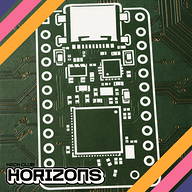
12/9/2025 - Rearranged PCB
Now that I've redesigned the schematic, I'll need to rearrange the PCB. Here are some key things I'm doing:
Minimizing space usage on the main board, compressing it to 34mm by 75mm. The USB-C breakout will be moved to the side of the board. And the LEDs for the Braille will also become a separate board.
The LEDs were placed according to the Braille on the Fusion CAD, and then I reassigned which LEDs were for each charlieplexed pin. I routed these. And, I routed the USB-C breakout. These were fairly easy and neither required any planes.
I switched ESP32S3 from having its antenna on the right side to on the left side, since previously the components on the top of the board were on the bottom of the ESP and vice versa. This required me to shift other stuff around.
I also wanted to modify edge.cuts to have mouse bites or something to make it easy to break away, but it looks like that might be a lot more work so first I want to see how JLC process it. So, I'll route the board first.
(Forgot to finish this before routing so the image is of the routed board)
12/11/2025 12 PM - Routed the PCB
I just connected a bunch of stuff and if they got in the way I moved it. I don't really know how else to explain it, so I'll attach images of various nets.
And here's a 3D view:
I locked in super hard so there isn't much else to say. I rearranged some stuff very slightly.
In terms of the edge cuts from the last post, I uploaded to JLC to see what they would do, and here's what I found:
they glue it together, so I'll just add a breakaway next time.
12/11/2025 5 PM - CAD update
Created PCB step and exported to Fusion, created a basic shell around it. I want the shell to magnetically pop off (or maybe unscrew, don't fully know yet) so there's no back yet. I also found a pretty big issue: the LED board and display overlap, which is bad. So I shortened the LED board and added a spacer so they don't quite overlap, and now it works out physically.
Also added the TARS ridge detail to the sides of the main body.
In terms of component placement (such as servos and speaker), I'll determine the best placement for those once components are received. This is to ensure that I don't need to worry about routing wires super precisely yet. Also, the WS2812Bs, in retrospect, don't really have a spot, so maybe I will need a strip of these and cut + paste them (ctrl x + v irl).
It also occurs to me that I don't want things moving around inside, so I need to add screws with heat inserts. Waveshare has terrible hardware documentation so I had to send in a support ticket asking what size their mounting holes were. For consistency, I'll use that same size for the rest of the PCBs, and I need to mount every single one with at least two screws, so I'll add those mounting holes next post.
Last things I did here were create cutouts in the body for the LED board LEDs so that the board could sit flush with the body instead of resting on top of it. You may realize that screws won't work because of the thinness of the shell and needing LEDs to be as close to the surface as possible. For this specific PCB I will glue it down, first with hot glue then with superglue. (Hot glue to hold it in place long enough for superglue to dry).
Note about those pins sticking up: they won't be there at all, I just had them there so that I could have mounting holes to wire to. The generated CAD just included them.
Action items for next post:
- PCB breakaway system
- back shell (screws or magnets)
- cutout for D pad
- mounting holes/heat insert sizing
12/15/2025 - Mounting Holes and Mouse Bites
They got back to me very quickly! M3 incoming
I first added mouse bites:
I aligned the boards to the grid (took forever), then drew 180º arcs. Between these arcs I added 1.0mm pads which have drilled holes. This was copy pasted four times to make the mouse bites. I then redrew edge.cuts.
I don't have space for the PCB to have M3. Also, the D pad needs to be very close to the surface, so adding heat inserts will hurt that distance. I need another way to mount this PCB.
I added the mounting holes for the display:
For mounting the PCB, I added these little tabs. The PCB fills the inside of the model fully so these are for vertical alignment.
12/16/2025 10 AM - BOM
Wrote BOM in Excel.
I updated my repo because I had neglected to do that previously. You should now be able to see my changes!
The journal is still empty on the repo for reasons I don't understand — if you're reading this on Blueprint then you're fine but nobody on github will see.
Clarifications: Notice I never wrote for the WS2812B. I will be using the strip and lining the inside of the robot with these, so no PCB/footprint is needed other than the header.
12/16/2025 11 AM - Fix mousebites
After receiving feedback in #electronics I'm switching my own mouse bites to the Panelization library's mouse bites by madworm.
I removed the pads I had placed before and adjusted the boards to be exactly 2mm apart, then added the 2mm mouse bites.
It uses layers I'm not familiar with, so let's break it down:
Here, we're looking at the smallest one. The yellow semicircles are silkscreen, so we can hide those for now. The small grey circles in the larger one are on the layer User.drawings, to provide the center of the large circles so that the edge.cuts can be drawn as such. These large circles are references, drawn on User.eco1 which has no set purpose. The small blue circles are drill holes, and aren't a specific layer, but they match the color of the mounting holes in the official library. Cool!
12/17/2025 9:47 AM - Fix PCB, update BOM and Readme
BOM: added heat inserts. Switched to Amazon to reduce price (cost from adafruit > additional cost from Amazon). The display is different from Amazon to Waveshare so I switched the display back to Waveshare.
Readme: added descriptions of hardware and more detailed descriptions of planned software.
PCB: realized that the switch is supposed to be diagonal so I rotated it by 45º and rerouted the board.
12/17/2025 9:57 AM - Fix changes
Added a schematic (see schematic.pdf).
I also added the ESP32 OTA example so that I have a base framework to start with once I get started on my project.
12/17/2025 10:35 AM - Update prices
Turns out, Waveshare only has suuuper expensive shipping options... so I found the part on amazon at the following link: https://www.amazon.com/gp/product/B0BFQF8GT3
Total price now is $152.
12/17/2025 10:38 AM - Update previous post
Accidentally doubled the amazon cost in BOM, fixed it to be single counted again. The new cost is $91.88 which is faaaaar better than the 152 that it was previously.
12/17/2025 10 PM - Add assembled image with components
This requires a lot of CAD as I don't actually have said image. So, here are all the things I'll need to add:
- Servos
- Move legs
- Add cutout for button (d-pad)
First of all, the d pad has no cad model that I could find. So, I'm going to make that (not too specifically though, its super complex). Then I'll download a servo model and implement it.
So, that's exactly what I did!