wisper
“A compact productivity device powered by an ESP32 or ESP8266. It features an OLED display, a set of physical buttons, and optional plug-in modules. The device can show the current time, run Pomodoro sessions, manage daily schedules with customizable time blocks, mute or filter notifications, and send alerts or emergency prompts when needed.
Created by
 Graphorn
Tier 3
52 views
0 followers
 CAN ⚡🚀
approved wisper ago
CAN ⚡🚀
approved wisper ago
Tickets awarded: 165 tickets
Tier: 3
CAN ⚡🚀
submitted wisper for ship review ago
Graphorn
added to the journal ago
assembling and coding
The final stage involved putting everything together and finishing the programming. For the assembly, I began by wiring all the modules. I connected the OLED screen, the buttons, and the LED to the NodeMCU. I didn’t have ready-made buttons with proper caps, so I took them from an old TV remote. I cut them out, made holes in the PVC case, and mounted them in place. After that, I installed the LED and carefully arranged the wiring to keep everything compact enough to fit inside the handmade enclosure. This step was still challenging, but definitely easier than building the case itself. It took about 1.5 to 2 hours to get everything properly fitted.
Programming was the real time-consuming part. The codebase grew to nearly 1100 lines. Writing all the features, fixing bugs, and troubleshooting required a lot of effort. The final debugging and getting everything to work smoothly took around 5 hours, in addition to the 2 hours spent assembling the circuit inside the case.
.png)


Graphorn
added to the journal ago
the making of the outer covering out of pvc pipe
The next stage involved building the case, and it turned out to be much more challenging than I expected. The PVC sheet I had flattened earlier was very brittle, so regular joining methods didn’t work. Hot glue wouldn’t stick properly, and even fast-setting super glue couldn’t hold the pieces together. I decided to try a different method. I used a soldering iron to melt and fuse the plastic pieces along the seams. It worked, but the process was slow, messy, and painful. I ended up burning my hands several times while trying to keep the edges aligned.
Once the pieces finally held their shape, the real struggle began: sanding. The inner surface had too many pores and rough spots, so I spent a long time sanding everything down with 250-grit paper just to make it usable. After smoothing the structure, I finally moved on to the assembly phase, which became the hardest part of the entire build.

.png)

Graphorn
added to the journal ago
I forgot to add the making of wisper so here it is
To start the build, I focused on shaping the physical design. I began by sketching the entire layout on graph paper. I planned the curves, dimensions, and cutouts I wanted for the final enclosure. Once the design felt right, I prepared the material. I took a PVC pipe and softened it by heating it gently over a gas stove, rotating it for even heat distribution. When the PVC became flexible, I quickly pressed it between two of my books to flatten it. This took several attempts because the sheet curled as it cooled, but I eventually got a perfectly flat piece. After the PVC cooled completely, I taped the graph paper sketch directly onto the sheet and used it as a cutting guide. With a cutter and sanding tools, I carefully followed the outlines and cut out each part of the de
sign.
Graphorn
submitted wisper for ship review ago
Graphorn
added to the journal ago
created the pcb and made a case
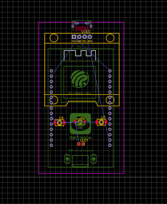
I created the PCB of the project in the EasyEDA software, and here are the diagrams. And I don't have enough money to buy a PCB, so I designed the circuit on a zero- PCB.
Screenshot 2025-11-20 103331


I also created a 3d case deighn that fits perfectly with the pcb here are some images of it


 Tanuki ⚡🚀
requested changes for wisper ago
Tanuki ⚡🚀
requested changes for wisper ago
repo has no cad
wisper was submitted for review ago
Graphorn
started wisper ago
11/20/2025 11 AM - created the pcb and made a case
I created the PCB of the project in the EasyEDA software, and here are the diagrams. And I don't have enough money to buy a PCB, so I designed the circuit on a zero- PCB.
Screenshot 2025-11-20 103331
I also created a 3d case deighn that fits perfectly with the pcb here are some images of it
11/20/2025 1:03 PM - I forgot to add the making of wisper so here it is
To start the build, I focused on shaping the physical design. I began by sketching the entire layout on graph paper. I planned the curves, dimensions, and cutouts I wanted for the final enclosure. Once the design felt right, I prepared the material. I took a PVC pipe and softened it by heating it gently over a gas stove, rotating it for even heat distribution. When the PVC became flexible, I quickly pressed it between two of my books to flatten it. This took several attempts because the sheet curled as it cooled, but I eventually got a perfectly flat piece. After the PVC cooled completely, I taped the graph paper sketch directly onto the sheet and used it as a cutting guide. With a cutter and sanding tools, I carefully followed the outlines and cut out each part of the de
sign.
11/20/2025 1:13 PM - the making of the outer covering out of pvc pipe
The next stage involved building the case, and it turned out to be much more challenging than I expected. The PVC sheet I had flattened earlier was very brittle, so regular joining methods didn’t work. Hot glue wouldn’t stick properly, and even fast-setting super glue couldn’t hold the pieces together. I decided to try a different method. I used a soldering iron to melt and fuse the plastic pieces along the seams. It worked, but the process was slow, messy, and painful. I ended up burning my hands several times while trying to keep the edges aligned.
Once the pieces finally held their shape, the real struggle began: sanding. The inner surface had too many pores and rough spots, so I spent a long time sanding everything down with 250-grit paper just to make it usable. After smoothing the structure, I finally moved on to the assembly phase, which became the hardest part of the entire build.
11/20/2025 1:19 PM - assembling and coding
The final stage involved putting everything together and finishing the programming. For the assembly, I began by wiring all the modules. I connected the OLED screen, the buttons, and the LED to the NodeMCU. I didn’t have ready-made buttons with proper caps, so I took them from an old TV remote. I cut them out, made holes in the PVC case, and mounted them in place. After that, I installed the LED and carefully arranged the wiring to keep everything compact enough to fit inside the handmade enclosure. This step was still challenging, but definitely easier than building the case itself. It took about 1.5 to 2 hours to get everything properly fitted.
Programming was the real time-consuming part. The codebase grew to nearly 1100 lines. Writing all the features, fixing bugs, and troubleshooting required a lot of effort. The final debugging and getting everything to work smoothly took around 5 hours, in addition to the 2 hours spent assembling the circuit inside the case.