Pepuino Nano V1
a dev board, that is ahead of its time, yehh it has a really really cool screens
Created by
 pipejosh
Tier 3
8 views
1 follower
 1mon ⚡
requested changes for Pepuino Nano V1 ago
1mon ⚡
requested changes for Pepuino Nano V1 ago
please dont submit for build review multiple times!
Tier: 3
pipejosh
submitted Pepuino Nano V1 for ship review ago
 m0.hid ⚡
approved Pepuino Nano V1 ago
m0.hid ⚡
approved Pepuino Nano V1 ago
Tickets awarded: 77 tickets
Tier: 3
Great work on this devboard! I love the silkscreen art you have on it
pipejosh
submitted Pepuino Nano V1 for ship review ago
pipejosh
added to the journal ago
The problem was solved
After some waiting, the resistors from aliexpress arrived, THEY ARE SMALL, i knew this was gonna be a challenge, but this was another level, i thought that me desodering this the old resistors was gonna be great headstart for future me, but turns out it wasn't i STRUGGLE for 3 hours straight trying to remove the soder from the small components even thought the resistor was not longer there, the soder path with soder was there, and with some flux i managed to leave it as flush as i could wihtout using the sodering wick or the pump and once this was done for all 5 borads, 2 resistors per board, came the actual hard part, sodering the new resistor, so now THIS IS THE STRUGGLE PART, and after 30 straight minutes just to soder the first resistor, i managed to somehow and with the help of flux and sodering paste, all the new resistors are in place.
So now that the new resistors are in place, i plugged it into my pc, and IT WORKED, i hold the reset button while connecting it, and the device show up, so now it was just a breeze to flash circuit python in 4 of them and kmk in the other one, for the keeb im gonna do, im really happy how this proyect turned out, i know now that i am for sure making a version 2 maybe with a esp 32????? or is im staying with this mcu i wanna add more features, a led for connection and a led for user control, integrated in the pcb

pipejosh
added to the journal ago
I f*cked it up
So after the initial hype of connecting a led to 3.3 and gnd and the light working, i wanted to flash some stuff into the board, the turorials where simple enough, hold reset connect to pc, and release the reset, well it wasnt working for me, so after some research and help from reddit, turns out in my diagram i made a fatal mistake, i used a 27k resistor instead of a 27 resistor, and that is quite a difference, so i orderded the new part from aliexpres, and in the mean time i decided it would be a good idea to desoder the resistors that i dont need so thats what i did.
I thought sodering the diodes for the split keeb was hard, HOLY desodering the resistors was hell, but after so much patience i managed to desoder them succesfully

pipejosh
added to the journal ago
The boards arrived!!
after some waiting time, the board finally arrived at my home, and they look so sick. the next step is to flash 4 of them with circuit python so i can program them later to fit my needs, and the last one, im gonna flash it with QMK firware beccause im gonna be making a keybaord out of it!!!!!!
i did a little led test to test the fact that they actyally work, and in fact, they do work
 CAN ⚡🚀
approved Pepuino Nano V1 ago
CAN ⚡🚀
approved Pepuino Nano V1 ago
Tier approved: 3
Grant approved: $83.00
Nice project
pipejosh
added to the journal ago
graphics are donee!
My girlfriend did an aswesome job at drawing the main component (a duck), and with the main character on scene, i just added words, with the title of the board, the creators, and the current version (V1) and with all that, adding into kicad as an svg was so easy literaly just import move and done, and with all that, see how much it's actually gonna be in jlcpcb
front

back

pipejosh
submitted Pepuino Nano V1 for ship review ago
pipejosh
added to the journal ago
Create the BOM
today i created the BOM that jlcpcb is gonna use as well as the position files they need, in other news, i discovered today that i suck at art, so i let someone expericed (my girlfriend) take over this part, beside this, i tried uploading it doing the BOM the positioning, and the pepuino nano is looking sharp so farrr!


pipejosh
added to the journal ago
Happy routingggg
todays was jsut routing the whole day, it was very very tedoius, but not as hard as i remembered, starting strong at the beginning moving components untill it all fit nicely, and the routed all as netly as i could

pipejosh
added to the journal ago
Creating the outline for the schematic
I spend today's day in creating the general outline of the pcb, i had a fun time, since it was jsu tmoving it aorund until i liked it, althought today was fun, i am sure tomorrow is gonna be hell (im gonna route the pcb tomorrow) but that sa problem for future me

pipejosh
added to the journal ago
Reseach for the name + create schematic + add footprintsss
Weeell here we go again, with another proyectttt, this time i wanted to learn more about dev board, and what a better way to learn than to make one myselfff, so i followed the tutorial (which is awesome and so well explained)
For the name, since the split keyboard im making is called the "pepito destroyer 3000" i wanted to call this board the "pepito destroyer 2000" but after some intense thinking, and will help from my girlfriend, we agreed on called it the "pepuino nano" (she doenst know im basically making a raspeberry not an arduino), once the hardest part, making the name was done, it was time to create the schematic, and with some help from the toturial, this was a breeze, i hope routing this will not be hellll
for the last bit of this journal, it comes the part of adding the footprint, there where a lot, but with some help from the tutorial, i could solve the problems and doubts i had

pipejosh
started Pepuino Nano V1 ago
12/23/2025 1 AM - Reseach for the name + create schematic + add footprintsss
Weeell here we go again, with another proyectttt, this time i wanted to learn more about dev board, and what a better way to learn than to make one myselfff, so i followed the tutorial (which is awesome and so well explained)
For the name, since the split keyboard im making is called the "pepito destroyer 3000" i wanted to call this board the "pepito destroyer 2000" but after some intense thinking, and will help from my girlfriend, we agreed on called it the "pepuino nano" (she doenst know im basically making a raspeberry not an arduino), once the hardest part, making the name was done, it was time to create the schematic, and with some help from the toturial, this was a breeze, i hope routing this will not be hellll
for the last bit of this journal, it comes the part of adding the footprint, there where a lot, but with some help from the tutorial, i could solve the problems and doubts i had
12/23/2025 9 PM - Creating the outline for the schematic
I spend today's day in creating the general outline of the pcb, i had a fun time, since it was jsu tmoving it aorund until i liked it, althought today was fun, i am sure tomorrow is gonna be hell (im gonna route the pcb tomorrow) but that sa problem for future me
12/25/2025 - Happy routingggg
todays was jsut routing the whole day, it was very very tedoius, but not as hard as i remembered, starting strong at the beginning moving components untill it all fit nicely, and the routed all as netly as i could
12/27/2025 - Create the BOM
today i created the BOM that jlcpcb is gonna use as well as the position files they need, in other news, i discovered today that i suck at art, so i let someone expericed (my girlfriend) take over this part, beside this, i tried uploading it doing the BOM the positioning, and the pepuino nano is looking sharp so farrr!
12/28/2025 - graphics are donee!
My girlfriend did an aswesome job at drawing the main component (a duck), and with the main character on scene, i just added words, with the title of the board, the creators, and the current version (V1) and with all that, adding into kicad as an svg was so easy literaly just import move and done, and with all that, see how much it's actually gonna be in jlcpcb
front
back
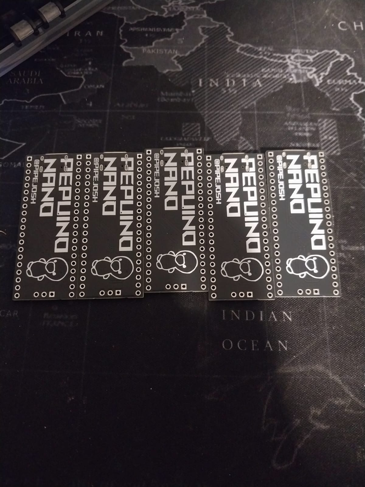
1/12/2026 - The boards arrived!!
after some waiting time, the board finally arrived at my home, and they look so sick. the next step is to flash 4 of them with circuit python so i can program them later to fit my needs, and the last one, im gonna flash it with QMK firware beccause im gonna be making a keybaord out of it!!!!!!
![image](/user-attachments/blobs/proxy/eyJfcmFpbHMiOnsiZGF0YSI6ODE2NjAsInB1ciI6ImJsb2JfaWQifX0=--18726fe6c7443d2be5eb2ed6f5d2dd62e1be0bdc/image.png
i did a little led test to test the fact that they actyally work, and in fact, they do work
1/14/2026 - I f*cked it up
So after the initial hype of connecting a led to 3.3 and gnd and the light working, i wanted to flash some stuff into the board, the turorials where simple enough, hold reset connect to pc, and release the reset, well it wasnt working for me, so after some research and help from reddit, turns out in my diagram i made a fatal mistake, i used a 27k resistor instead of a 27 resistor, and that is quite a difference, so i orderded the new part from aliexpres, and in the mean time i decided it would be a good idea to desoder the resistors that i dont need so thats what i did.
I thought sodering the diodes for the split keeb was hard, HOLY desodering the resistors was hell, but after so much patience i managed to desoder them succesfully
1/29/2026 - The problem was solved
After some waiting, the resistors from aliexpress arrived, THEY ARE SMALL, i knew this was gonna be a challenge, but this was another level, i thought that me desodering this the old resistors was gonna be great headstart for future me, but turns out it wasn't i STRUGGLE for 3 hours straight trying to remove the soder from the small components even thought the resistor was not longer there, the soder path with soder was there, and with some flux i managed to leave it as flush as i could wihtout using the sodering wick or the pump and once this was done for all 5 borads, 2 resistors per board, came the actual hard part, sodering the new resistor, so now THIS IS THE STRUGGLE PART, and after 30 straight minutes just to soder the first resistor, i managed to somehow and with the help of flux and sodering paste, all the new resistors are in place.
So now that the new resistors are in place, i plugged it into my pc, and IT WORKED, i hold the reset button while connecting it, and the device show up, so now it was just a breeze to flash circuit python in 4 of them and kmk in the other one, for the keeb im gonna do, im really happy how this proyect turned out, i know now that i am for sure making a version 2 maybe with a esp 32????? or is im staying with this mcu i wanna add more features, a led for connection and a led for user control, integrated in the pcb