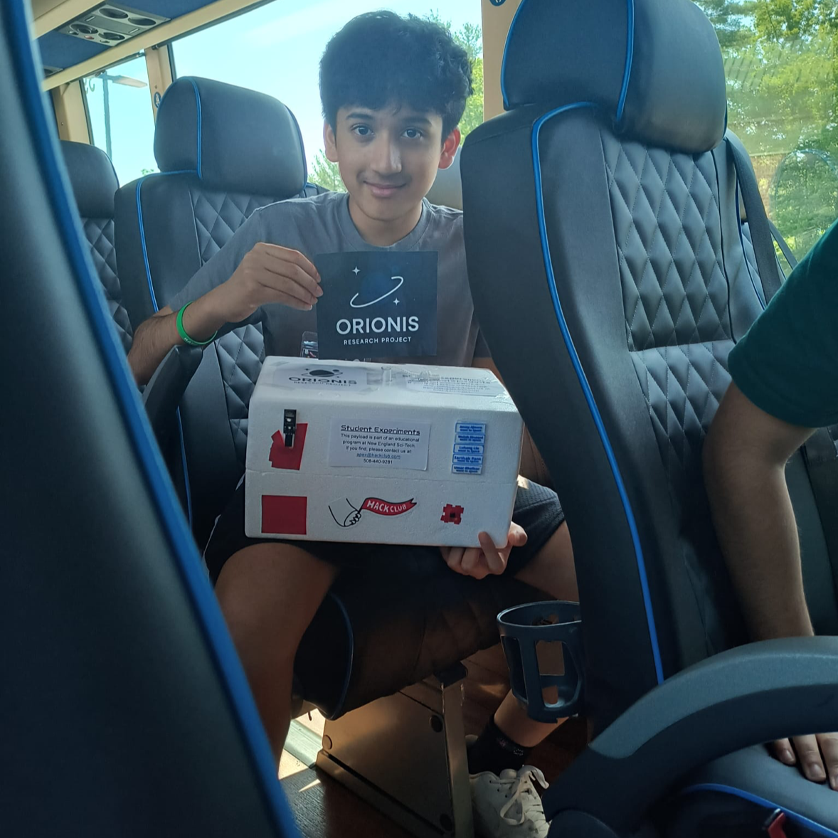
RoboCup Junior Rescue Line Robot
Description: Hey! Our team of 3 (with me submitting) will spend this school year working on a robot for RoboCup Junior's Rescue Line challenge. Our competition will take place in April, and our goal is to secure first place, allowing us to compete internationally at the RCJ 2026 event in South Korea. Here's a rough timeline for us so far: August: Planning Stage September–October: 3D Modeling October–December: Building January–April: Coding and Testing Why: We're interested in being involved with robotics without needing an FRC-level commitment, but without control over what gets done. RoboCup Junior is the perfect solution to this, as we can stay a team of 3, contribute to all parts of development, and focus our software on AI-powered models for line following and victim detection. We want to participate in Blueprint to secure funding for some of the components that go into making this robot, including motors, a Jetson Nano, batteries, and other external supplies. How: Our robot is specifically designed to be able to traverse the full RoboCup Junior Rescue Line map. To use the motors and various sensors on our robot, you have to turn on the main switch that gives power to the motors and Jetson Orin Nano. We extended the HDMI and USB hubs using extender cables to access them when the robot is fully built. From here, since we're using a Seeed Studio for PWM, the servos and motors can technically be accessed through VS Code on the Jetson interface. As for all of the sensors connected directly to its 40-pin header, those need to be accessed using terminal commands. We're working out a better solution soon to make this easier (all of us are still learning). How to build something like this yourself: This robot was definitely a complex process for us! If you want to make something like this yourself, you should first spend a good amount of time deciding what your robot should be capable of doing. From here, you can start designing a CAD model, which will take many, many iterations. If you did it in the first try, there's a very good chance that it can be made better. THat's why the 3D Modeling stage took a LOT of time for us, as we iterated, printed, tested, reprinted, and eventually got everything to work. Now for the fun part, you can physically build the robot once you printed all of your parts! This is where a BOM became very important for us, as we needed to track how we would split the cost, how Blueprint would cover it, and what we recieved and what we have left to buy. Once you get all your parts, you can start making a basic wiring diagram to see how you will connect everything together, to avoid making a mistake and then having to restart. It will take a while to go through the building process, making sure each joint is perfect, testing continuity, perhaps remaking a CAD model if something goes wrong, and finding the best way to organize parts and wires. We had a giant Jetson Orin Nano at the center of our robot so it was especially hard for us. Finally, once the robot is done, you can start coding, and that's where we're at right now at the time of writing this!
Created by
 Anvay Ajmera 🚀
Tier 2
84 views
0 followers
 alexren ⚡🚀
approved RoboCup Junior Rescue Line Robot ago
alexren ⚡🚀
approved RoboCup Junior Rescue Line Robot ago
Tickets awarded: 1263 tickets
Tier: 2
sorry for taking so long to get to this! enjoy the tickets
Anvay Ajmera 🚀
submitted RoboCup Junior Rescue Line Robot for ship review ago
Anvay Ajmera 🚀
added to the journal ago
While we were testing, the arm snapped off, w/ other issues
We met up and tested for around 3 hours (1.5 hours of that was dedicated active work).
Issue 1: arm snapped off, it was way too thin and needed to have higher infill when printing. This shouldn't be too hard to fix in terms of hardware.
Issue 2: the servo that is connected straight to the jetson pwm (and not seeed studio) seems to have it's signal floating when the jetson turns on, causing it to go crazy. We need to see what to do abt this.
Issue 3: light seemed to turn off after 30 min, maybe a 1 time issue?
Issue 4: our new code isn't that great.

Anvay Ajmera 🚀
added to the journal ago
Finished building robot with a 3rd platform, + arm
We decided to take a pause on testing for now and in the meantime, finished building robot fully.
I started off by trying to figure out how to organize the mess of the wires that is clearly prevalent in the earlier pictures. I had to figure out how to get all 4 servo wires into one designated place to connect 5v, gnd, and signal, and eventually found a spot I could trust to hot glue everything. I realized that the motor gnd had to be connected to the jetson gnd. this was a major oversight that showed why my servos weren't working properly that I was trying to debug for over 30 minutes.
Anyways, from here, I added on the 3rd platform. Now, for the arm, I was facing an issue because the lights we got have this metal plate that gets insanely hot after around 10 minutes. If the servo sat right on top of that, it seemed dangerous. So, I put around 4 layers of neoprene rubber. It wasn't the best choice as it collected the heat, but it was significantly less hot to touch now, and gave the servo mount something to grab onto. From here, I could properly attach the arm to the arm servo, and make sure that it could successfuly move back to the 3rd paltform without getting stuck within the wire mess. Zipties helped a lot.

Anvay Ajmera 🚀
added to the journal ago
1/24/26 We think we found a final strategy now (hopefully)
Testing a completely new system
Now, only read the contour of the bottom 60% of the screen called ROI
Prevents the robot from being affected by stuff happening too far into the future
Find middle of contour, distance to center line represents offset error
Positive error -> turn right
Negative error -> turn left
Now synonymous with the setmotoroutput
cv2.FitLine on the contour returns vx,vy,x0,y0, representing the vector of the line of best fit of the contour as well as a point (x0,y0) on the contour
Added contours plus the line to the debug window
Drawing a line with the vector is not trivial
Put it in a function called draw_fitline
First, take two y values, top and bottom of the ROI
Use the vx and vy as a slope to calculate corresponding x values
Now you have two points to draw a line
Worked decently well but failed on sharp turns
Attempted to add angle
Fetched angle of line relative to the center line using atan, but doesnt work
Line of the path can go either way, and the angle changes as a result
Both situations have the same line, with the same vx/vy, yet the angle that the robot needs to turn is completely different
New strategy, store previous starts and end of the line
Extrapolated the start ane end from the draw function, now returns those two points
Save those two points to two fields on the robot, r.ltstart, and r.ltend
Linetrace function now returns those two points as well, and loop stores those points into the fields on the robot
The fields on the robot are passed to the function and thus represent the state of start and end on the previous frame
The new start and end of the line now are calculated based on whichever point of the line is closest to the previous start and previous end respectively
If the first point of the line is closer to the old start, the new start would be that, otherwise it would be the second point of the line
Same logic for new end
This logic works as the change in distance for the start point and end point is never too drastic in between 2 frames, ensuring stable continuation
Gap logic is inherently handled, as the start and end point of the islands of a gap would be similarly spaced apart from previous start and end points, or, in other words, d2 is always greater than d1, thus the start and end points remain accurate through gaps
Further refinements will be needed for when there are large gaps in the black line, the slivers of gaps in between tiles that can potentially be detected as the black line, and result in the robot wandering off (set a higher minimum pixel area for contours to be classified as the black line, or require all parts detected as the black line to have a minimum thickness)
Having access to the start and end of the line changes the algorithm
First calculate vector v from start to end
Converted start and end to np arrays
Then subtract the np arrays to get vector
Conveniently np has @ for dot product
Use dot product formula to calculate the angle between that vector and the middle of the screen
Middle of screen is (0, h) where h is the height of the frame
Angle = acos (v @ mid / (||v|| * ||mid||))
Now that gives an angle from 0 to pi
The angle must be changed depending on where start and end are different. Two scenarios
Check y values of the points
If start is below end then nothing changes
If start is above end then the angle is now pi - angle
Check x values
If start is to the left of end then nothing changes
If start is to the right of end then the angle must be negative, because the robot must turn left to adjust for that
KEY CATCH -> opencv frames increase in y value going down, so below and above must be reversed
Had to fix some small errors where the drawfitline was returning points in the wrong order
Angle is now accurate with the way the line is going
Angle is added to control for PID, multiplied by an ANGLEMULTIPLIER which is in the constants.py
Allows us to adjust how much the angle matters relative to the offset
Tested new code
Almost works, but there's some weird edge cases for horizontal lines, where the offset just gets extremely big, and breaks the code basically, likely due to how the offset is calculated based off vx and vy, which breaks on horizontal lines
Going to address that by using moments and COM instead
The offset bugs SUCK bro but everything looks promising

Anvay Ajmera 🚀
added to the journal ago
1/18/26 Got Remote deployment working + line following
Remote SSH on vscode works really well
Switched to VSCode because Pycharm was inconsistent in a variety of ways
Pycharm remote development relies on creating a temporary folder
The terminal is awkward to use in pycharm
It takes a while to launch each time, as the temporary folder gets wiped often, leading to over 30 minutes of waiting each time just to try and deploy
Moved all the classes in python to their own lib module
Fixed a circular import in the motor / robot class
Merged serialComms code with main after fixing some really weird edge cases
Merged main with line trace to have latest library settings, still deciding on how to structure code
Function files will either be used in Robot, or function files will use Robot. Leaning towards second option at the moment
First option allows robot to have update and init functions, makes main.py extremely concise, maybe just robot.update(), BUT robot.py will be extremely cluttered
Arduino IDE style
Second option spreads the code out more, each function file will have robot.py imported to have access to robot functions, and can be called in main.py, spreads code out between main.py and function files
Added PID control to robot.py
Can be accessed through any robot object, and gives an output currently only for motors
Added setleftmotors and setrightmotors for robot.py
Simple access to both left and right motors, saves some clutter
Added setoutput to robot.py
Allows us to pass in some control output to the function, the function will pass it through the PID automatically, and push that output to the motors
Motor output works like this
Base speed u
Subtract output from left motor, and add output to right motor
Positive output -> turn right
Negative output -> turn left
Added two cameras to robot.py, ballcam, and line_cam, respectively
Expanded upon the linetrace functions
GUI constant controls whether to render cv2 windows for headless running, allows for simple testing through remote SSH
Linetrace now automatically connects to the line camera and tries to line trace off of it
Tested line trace
Not successful, seems to just not properly follow the line
Sometimes one motor just doesn’t turn on?
Weird bug that causes seeed studio to stall too
No way to bootselect besides just turning off and on the jetson which sucks
Goals
Fix the bugs with line trace
Fix seed studio bug
We also decided to look into more strategies: Tested some experimental features with line tracing on Linetrace-exp branch
Check top third of frame, left third and right third
If top third is empty, then turn left or right depending on if left or right third is empty
Worked, but still didnt solve the issue of the sharper turns
Fixed errors with the setmotoroutput
Directions were reversed
Added constant MOTORS to constant.py that represents whether the motors are on or off or not
Allows for easy testing of error and values through cv2
Goals
Test some other strategies

Anvay Ajmera 🚀
added to the journal ago
1/16/26 Fixed some small errors with the arduino code

Code requires yield() function for some reason, otherwise it just breaks while reading
Updated the serial communication to use 6 length byte array
Fifth byte is for sign
Updated the serial comms to turn on motors
Fifth byte decides whether or not to turn the motors negative or positive
Arduino reads six bytes, determines whether or not to send a negative speed into .setSpeed on the motors
Now motor works for both forwards and backwards
Updated classes to Jetson for motor control
Motor class now just takes in an id, representing the id sent to the Seeed Studio
The set speed functions handles all logic for sending the correct sign byte, and sends the bytearray
Added motors to Robot singleton
Robot singleton has motors[] array that have .set_speed() on them
Each motor has a reference to the Robot’s serial manager, and calls the send function on that to work
Allows every other class to access the motors
Attempted to get remote deployment working
Pycharm remote interpreter set to ssh into Jetson
Ran into a variety of issues
Changed the project to rely on modules instead, still can’t import some things though
Will have to test more
Added simple-pid module to jetson, will function as our pid controller
PID architecture is simple, output of PID will be used to add and subtract to base speed of jetson motors
Base speed + output for left motors and base speed - output for right motors.
Goals
Integrate with my code and test the line tracing fully
Get remote development working
Anvay Ajmera 🚀
added to the journal ago
1/14/26 Modified earlier linetrace functions
Thresholds camera feed to a black line mat through OpenCV binary thresholding
The binary threshold returns separate contours of the image (shadows, small specks on the paper, etc), so the code has to iterate through the different contours to only check that with the largest area and set that as the black line
Additionally, when there are gaps, sometimes there is no black line visible, and the largest contour isn’t actually the black line
In these cases, there is a minimum threshold of pixels for a contour to be considered the black line
The mat of the black line contour is displayed for debugging
Currently, this function works with webcam feed but remains untested with the cameras on the robot
Right now, the function automatically sets the width and height to 640x360, but this may be changed in the future if it doesn’t match our cameras input feed dimensions
Calculates the center of mass of the black line mat
The centroid of the line is calculated here
The point of the centroid is then compared to the value of half the width of the camera feed (the middle of the screen) to determine how far off the robot is shifted from the line
Sends over integer offset values to be used for motor controls
In summary we obviously didn't have a robot when making code before but now it's a lot more clear
Anvay Ajmera 🚀
added to the journal ago
1/13/26 worked on code structure in jetson/seeed
Here is what we did in detail:
Arduino has a Robot class singleton, that has access to four motors, and functions for reading serial input
Has update and setup functions for loop and setup respectively
Singleton works though a static function getRobot() that checks if an instance has been created already and if not it will otherwise, it will return the already created one
Jetson has Robot singleton using python classes too
Uses new constructor to check if an instance has been created yet
Will control everything and have access to all sensors, thus all other files can access the singleton
Added constants to both Arduino and Jetson for easy constant updates
constants.py in Jetson and constants.hpp in Arduino
pAllows us to store the command hex codes and ports and baud rates etc.
Setup serial communications between Jetson and Arduino
Jetson uses Serial module to communicate with arduino on port /dev/ttyACM0 and baud rate 115200
Communication uses byte array
First byte is a command byte, 0xAA, signifies start of command
Second byte determines what command, the commands are stored in constant files
Third and fourth byte are arguments
For setting motors, its the motor number and speed
Fifth byte is verification byte
Xor of the first four bytes, checks if the command has been corrupted or not
Jetson simply creates a byte array and sends the commands to Arduino
Created Serial Manager class that sets up the serial port and has functions to send commands
Arduino is constantly listening, and flushing to a buffer, which represents the byte array
If the buffer fills and the start command is detected, it will trigger the corresponding command

alexren ⚡🚀
requested changes for RoboCup Junior Rescue Line Robot ago
hey there! sorry for the wait
first off - AMAZING job on the journal! seriously love the detail with everything and i think it's cool. I would be more cognizant of the time tracking though - everything feels a little inflated?
more importantly though, you don't have a detailed wiring diagram! we can see the general connections, but that doesn't really explain what wires go where. A good way to tell if a project is shipped or not is to ask yourself if you could reasonably recreate it from information only in the repository.
let me know if you have any questions!
Tier: 2
Anvay Ajmera 🚀
submitted RoboCup Junior Rescue Line Robot for ship review ago
Anvay Ajmera 🚀
added to the journal ago
Made map with our team
Made map - we also had to make an initial testing map we will train our model and code on. Mock picture of a few tiles is attached below.

We are at a point where we just need to add our arm/claw, along with our ball platform, and we will be completely finished with our build! From there, we can use this map we made to begin OpenCV, YOLO v8 models, and whatever else we need for the final product in preparation for April.
Anvay Ajmera 🚀
added to the journal ago
Added wheels, made map, switched servo, and COMPLETE (almos)
Now that basically everything was wired up, there were a bunch of tasks we completed over the past week (it was really spread out and random so i decided to fit it in one entry)
Here is a list:
1: Switched relay - whether it was the logic of the relay, I simply didn’t like it due to its size. I switched it, tested it, and it works with the Jetson orin nano now.
2: Added wheels - there was an entire issue regarding this because the screws #4-40 that came with the Polulu wheels wore out way too easily. So I had to buy silver ones from amazon which ended up working.
3: Fixed up wiring
4: tested code with wheels, i2c devices, etc


Anvay Ajmera 🚀
added to the journal ago
Continued to wire up everything above the plate and wheels
I continued to wire everything up, including using a dupont wire for the relay and then stripping it and connecting/soldering the wire to the part needed like my LEDs and then 12v power source. I also made super cool logos for our team (we're calling it Overdrive) and attached them to the wheels to give the robot a better overall look. I ran final tests again after this!

Anvay Ajmera 🚀
added to the journal ago
Attached relay, buck boost converters, and soldered + wired
Now that the front plate was on, I could start screwing in the buck boost converters and the relay in their designated spots. I could also attatch the LEDS, and solder the wires so that the motors would recieve power from their own battery source. I also cleaned a few extra things up, and ended up running tests to make sure everything was still okay.
I had to fix an issue where the jetson had no place to expel its hot air, and I kind of fixed it for now.

Anvay Ajmera 🚀
added to the journal ago
Finally put chassis plate on the robot and cleaned wires up
Since I now have an entire Seeed studio board I needed to fit somewhere along the jetson, it was harder to get the plate to fit, and it didn't fit perfectly. However, I was still able to, along with getting the wires for servos, relay, etc to be accessible, along with the jetson hdmi and usb ports by utilizing our insanely smart grid design to ziptie them. 
Anvay Ajmera 🚀
added to the journal ago
bad PWM issue --> had to plan out, fix, and ran tests again
Basically, what happened is that I realized that the Jetson Orin Nano had a severe lack of PWM pins. I needed at least 8 to account for my motors and servos in the robot, and I knew I had to find a different board that I could hopefully connect via the extra USBC port in the jetson that was available. Coming back from prototype, I realized that the SEED Studio RP2040 was the perfect solution, so I ordered that and got everything set up.
The issue we came across when using this was that initially, the direction pins of the DRV8871's were just not working at all. I learned that this was likely due to the fact that the RP2040 had two channels and I had to put a motor driver in a single channel (I think). That ended up fixing it, and my tests went well then.
This log took a lot of time to figure out what the issue was btw it was really annoying

Anvay Ajmera 🚀
added to the journal ago
almost done with base chassis wiring (pt2 of saturday)
I got a quite a few things done in this journal
- attached all wheels properly which took a LONG time to do because of the tiny and annoying provided hex screws that basically wore out instantly
- labled everything that would be useful to refer to
- officially placed the drv8871 motor drivers in the most optimal spots, and used hot glue along with zipties when necessary to make the wiring secure and optimized (this took majority of the time due to the amount of iterations done)

Anvay Ajmera 🚀
added to the journal ago
worked with motor drivers --> finished ALL base wires (pt1)
I finalized the DRV8871 as our new motor drivers due to their higher peak amp capacity and their ability to turn the motor power source to a logic power source all with 1 wire (also, I realzied that having 4 flexible motor drivers is better than two motor drivers with too many wires to move). I made the strategy of removing the plastic shelling from 22awg dupont wires, and using dupont wires + hot glue for logic (I kind of regret this now since male dupont thing is really weak, but it's fine because this part of the robot will be enclosed to resist any harsh pulling).
In my next journal I will connect everything.

Anvay Ajmera 🚀
added to the journal ago
Tested all motors with wheels after one was behaving weird
I noticed that when I was resoldering the wires to a motor, when given 12V power, it was making a really weird and disturbing clicking sound. Now, all of them seem to work, but two make noises that the other two don't. I am not sure if this is a motor issue or the solder issue (I don't think it's a solder issue), but at least they all seem strong.

Anvay Ajmera 🚀
added to the journal ago
Placed mux in the best position possible to make wiring neat
During the wiring process, after getting the new frame, I had a perfect spot in mind to place the mux (this is what centralizes the addresses of 4 distance sensors, an MPU6050, a OLED, and a grove port to female dupont pins to connect straight to the jetson orin nano).
It took a lot of effort to get the placement done since I originally did this with the old frame, used heatshrink for all STEMMA wires, and finalized how I would go about the solution. But, when taking the parts out for the new frame, the motor wire came out and was honestly behaving weird when given 12V, but I was able to fix it (hopefully it stays fixed).
Anyways, I finished the placement with the new frame after:

Anvay Ajmera 🚀
added to the journal ago
Big frame change in order to adapt for new wiring strategy
We realized that our old frame looked fancy, but was not suited for the changes we wanted to make. Below are the key problems listed:
-Made the wiring and placement of the buck boost converter to the buck converter very awkward
-Covered certain Jetson Orin Nano pins because we were originally going to use an Arduino nano --> but, due to the switch since that is no longer needed, the frame needed to be changed anyways
-Started to look chopped due to the amt of holes I drilled to account for all the random changes we had
As anyone would, the problems made it clear that it was worth to disassemble a lot of what we had to have a new frame. We realized that we needed a way for our ports (2 USB, display, USBC) to be avaliable to us while the jetson orin nano is packed in the center of the robot. The image below shows what we did (took 4 hours of CAD + call): 
Here are pictures we edited during our group call:


Anvay Ajmera 🚀
added to the journal ago
Interconnected ALL parts
Now that the switch issue is fixed, and I got the other parts I need, the last part to connect is the motors to the motor driver, the servos, and minor logic connections. Other than that, I started planning out how I would fit and place all these parts onto the robot in a safe way.
Anvay Ajmera 🚀
added to the journal ago
Completely fixed connection strategy for main switch
If you scroll down in this journal to where the switch was first soldered to other wires, it already looked dangerous, but at the time I thought that it worked. However, when using the Jetson, it started sparking for no reason, even though ground and voltage never touched. Either way, I knew I had to fix those connections so learned how to use crimp connectors with my own wires. After a lot of experiments, I fixed our connections around the switch! 

Anvay Ajmera 🚀
added to the journal ago
Continued to wire, glue, and zip tie mess
In my last log I made most of my connections to the 40 pin extender of the jetson orin nano. Now, i’m continuing to wire the sensors up, specifically focusing on the I2C connections and mux this time. You might also notice that I attached the front plate with screws too, and even put on and found the best way to have the batteries on the robot.


Anvay Ajmera 🚀
added to the journal ago
Connected motor driver to 40 pin jetson extender
I connected all of the necessary motor driver pins to the jetson orin nano extender and glued it on (allowing me to keep all wires secure without ruining the jetson at all). next, i’ll continue to do the same thing with the mux, relay, etc.


Anvay Ajmera 🚀
added to the journal ago
Created a plan for how I would use motor drivers
To have the robot actually start driving, I believe the next best step is to work on and connect the motor drivers to the motors and Jetson Orin Nano. However, the problem is that my dupont wires are not good enough to handle 12v at 2-3A. This meant that I had to come up with a plan to somehow connect bare wire to the dupont pins of the motor driver. I was somehow able to wrap around the bare wire around a pin, apply solder carefully, and then put a heatshrink on top of it. I did this for the voltage and grounds of two motor drivers. Then, I planned out and attached all other necessary wires.

Anvay Ajmera 🚀
added to the journal ago
Tested all connections for continuity
I realized that it was important that I test all my connections for continuity to make sure that some weren't bad. Thankfully, I found out that one wire connected to my touch sensor wasn't soldered well and I was able to fix it.

Anvay Ajmera 🚀
added to the journal ago
Tested distance sensors with front bumper + tested wheels
I needed to make sure that the distance sensors were at the perfect positioning to work. So, I screwed the wheel mounting hubs onto the motors and tested the distance sensors (ToF) with a mux to see if it could detect obstacles and if it would be feasible in code. From what I tested, it seemed to work well for now.

Anvay Ajmera 🚀
added to the journal ago
Fixed issue regarding the USB cable of camera
If you look carefully at the camera two logs ago (where I show the robot assembly in progress), you can see that the camera had 4 wires that are in a secure cable with aluminum paper covering. THe issue was that this cable was so thick that it was taking way too much space from the robot. So, I made the tough decision of cutting it to the point where I just had those four wires. However, when stripping the wire to reveal the bare metal, I accidentially took off the white one entirely. So, I had to carefully solder it back on and test for continuity using a multimeter. It works! I did have to buy a replacement USB to 4 wires from amazon though.

Anvay Ajmera 🚀
added to the journal ago
Brutally drilled through all mounting hubs and built wheels
After spending nearly an hour trying to figure out why my screw types weren't working at all on the universal mounting hub, I decided to try using my 3mm drill bit thru the hole to see if it would help. While it was a huge hassle, since sometimes the entire hub would start moving in a circle, I was able to succesfully drill all holes in all hubs and attach the M3 screws I have onto the wheels + hub.

Anvay Ajmera 🚀
added to the journal ago
Start assembling and putting components together on chassis
The time has come! Now that we have fully finalized the major components in our current CAD model, I can start to reassemble and put together the parts on the robot. In this image, the back plate, motors, jetson (with all cables) and front plate have all been attached and assembled. 
There were times when I needed to solder a bit of the CAD off to allow wires (something we didn't fully account for when making the CAD model but it's okay).
Anvay Ajmera 🚀
added to the journal ago
Fixed previous code fake green square algorithm in map
Building on what we learned before, the yellow dot also has a very important role

In RCJ linetracing, some green squares are fake, as they are on the other side of the horizontal line in the intersection (meaning the robot should ignore it)
The yellow dot helps to check
If the yellow dot is located over the black line, it means that the green square is located above the black line
This means the green square is fake, and won’t be considered
However, the robot still has to turn if a real green square is also located in the intersection

this still needs a lot of refining but it's a good place to start
Anvay Ajmera 🚀
added to the journal ago
Nearly finalized green square detection algorithm
When there is an intersection, we have to check for green squares
Detecting them is relatively simple, just check for a large group of pixels with greater green value than red and blue values
However, the location of the green square relative to the line matters
If its on the left side, the robot must turn left, if its on the right side, the robot must turn right, and if it’s on both, the robot has to do a u turn
To determine what side a green square is on, we draw out 4 points a set distance from the center of the bounding box of the green square

The code checks the 4 dots (pink , blue, green, and yellow in this image)
If both the green and blue one are located over the black line while the green is not, it means it must be a left turn, as the green one is on the right side of the green square, thus meaning the green square is on the left side of the line. Vice versa, if both the blue and pink ones are over the black line while the green is not, it must be a right turn.

Anvay Ajmera 🚀
added to the journal ago
CODE WORK --> wrote out code plan
We reviewed our linetracing plan from last year, and evaluated what we could improve upon this year
Ultimately, the following plan was drafted:
Line following
Accounts for green square, follows black line, etc
Linetrace is based off of the OpenCV Mat containing all the pixels for the black line, we can use a more complicated algorithm (not just center of mass)
For green squares, we can have the robot turn using the gyro, or remove the other parts of the intersection so it only sees the correct path, and just does normal linetrace based off of that
Obstacle avoidance
When obstacle is detected through the front distance sensors, the robot will stop moving and go around it
To maintain a constant distance from the obstacle, we use the side distance sensors
During this process, the robot must actively be trying to refind the black line
Due to the nature of the turns, the robot cannot resume line following immediately after refinding the line, it must perform a turn before continuing line following
Once the silver line is detected (linetrace code must continually check for the silver line)
Robot enters the victim stage
Keeps turning until a victim is detected
If multiple are detected, go towards the one with the largest bounding box (the closest one)
Approaches the ball until a certain threshold is reached (we can estimate distance from ball by finding the area of the ball onscreen placed at a set distance away from the camera, and because the area is inversely proportional to the distance from the ball, we can estimate pretty accurately how far the ball is from the camera)
collectBall() function that sends the commands for the motors to pick up the balls. This can be done with delay() or encoders doesn’t matter too much
We use touch sensors on the claw to confirm the claw has a hold on the ball and when the touch sensors are released, confirms that the ball is deposited into our third platform
(and a lot more)

Afterwards, we all agreed on this plan
Anvay Ajmera 🚀
added to the journal ago
Needed to remove all pieces from robot, then worked on oled+
As part of our three-member squad right now, one person is testing out OpenCV code, the other is working on CAD + code, and I, the person who is writing this, am working on CAD + hardware. We had a really long discussion about changing a lot of the CAD model but then eventually came to the conclusion that it was not worth doing all of that to save 1 centimeter of length. So, we changed our distance sensors but kept mostly everything else the same.
Since we are using a mux now, I realized that I had a oled screen with a Mux connection. However, the model didn't account for that, so I bascially just drilled a bunch of holes near there until I was able to fit the wire through. I also added the click sensor on the back of the robot

Anvay Ajmera 🚀
added to the journal ago
Added touch sensor to claw to detect ball accurately
(other teammate work)
Changed claw design, adding a push button to confirm that the ball is grabbed and secured.
Printed and tested the mechanism to ensure it’s functional
Used code to put it under different scenarios.

Anvay Ajmera 🚀
added to the journal ago
Changed CAD model from distance sensor to touch sensor
Added push sensor behind the robot, replacing the distance sensor
Because the distance sensor can only detect distances above 2 cm, and we need a sensor to confirm if the robot is in contact with the victim evac zone, a push sensor would be more effective/easier to code

Tested it after
Anvay Ajmera 🚀
added to the journal ago
Designed new frontplate
Problems with old front plate
Distance sensors were positioned forward, meaning thinner obstacles might not be detected
Victim camera was positioned too forward, forcing us to increase robot length as the linetracing camera has to see ahead of it
New design used angled distance sensors that would detect when an obstacle was directly in front of the robot
This also lets us validate the obstacle using the gyroscope, as when the robot is stuck, the gyroscope will show low acceleration
The victim camera is moved backward to give more space for distance sensors
Anvay Ajmera 🚀
added to the journal ago
Made brutal change to the distance sensor & made I2C strat
(worked on by all 3 teammates)
We ended up testing our previous distance sensors (cheap ones) and realized that they were horribly inaccurate, even when "calibrated". This scared us and led us to look into the sensors used by previous teams. After research and emailing, we got a call from the team that placed 2nd internationally in 2025. We were informed that they faced a similar problem, and that they used the VL53L0X sensor. So, after a lot of conversation, we decided to do the same thing.
As we developed our solution, on CAD, we changed the distance sensors to our more reliable model. A hole was added to the battery mount to allow for the wires from the distance sensor to travel directly to the center of the robot, where it would connect to the jetson orin nanos pins.
We also finalized how we would go about using I2C, as all parts needed a unique way of being functioned. The picture below shows an example of what we planned out using a mux (with ONLY the Xshut pin soldered).


Anvay Ajmera 🚀
added to the journal ago
Designed and printed map parts
(completed by teammate and I)
We spent this time looking into competition rules, and the specs of the maps, including ramps and obstacles. We want to recreate identical maps when we start coding and testing, so that meant we needed to CAD map accessories (so we don't have to buy the expensive ones). We needed a good way for this to work, so after many iterations, we came up with a LEGO style approach, where we can screw on more pieces (as shown below) to increase the height of the ramp. We also made a hinge mechanism for the seesaw, and printed it. It ended up working successfully, but we still have to fully test it with the robot.

)

Anvay Ajmera 🚀
added to the journal ago
Iterated through how LED would be attached to CAD model
(completed by teammate)
My teammate spent a long time trying to perfect the CAD on how the LED would be attached to the robot. There were numerous options we went through, including solder, tape, just a fire CAD design, but then we landed on zip ties for now, that produced the result shown below. We also tested the LED by connecting it to a relay, which was connected to a stripped USB.


Anvay Ajmera 🚀
added to the journal ago
Tested motors and motor drivers together
After figuring out the issue with the motor drivers, I fixed all of them, wired them, and started running numerous tests on the motors. We also learned that each can support two motors so we adapted for that in the future. Our numerous tests proved successful, and now we just have to figure out where we can stuff the motor drivers in the internal robot CAD.

Anvay Ajmera 🚀
added to the journal ago
Tested and fixed motor driver problem
Originally a few months back I wasn't sure why these motor drivers weren't working. I ended up finding out I can't just solder the corners and assume that the conductive parts are touching, and that I have to solder every single pin. After learning this, I resoldered these motor drivers, and they work now!

Anvay Ajmera 🚀
added to the journal ago
Finalized LiPo Charger
(PARTNER WORK) Our original one didn't work so we looked throughout Amazon to find a good LiPo charger. We chose this one, and it was absolutely amazing (50W per hour)!! The UI was great too.

Anvay Ajmera 🚀
added to the journal ago
Finalized Display Port wire (sob)
This one was a nightmare. So, we knew that we were NOT going to rely on something like VNC Viewer on competition day (if ykyk) and the clear path to take was the old keyboard and mouse route. However, once the robot was built, these ports would be completely inaccessible, meaning we needed extender wires attached to the ports beforehand that come out to an external point of the robot that we could access. Originally, I thought that the Jetson Orin Nano was going to use an HDMI port. But, after taking a closer look, it was a Display Port. The problem with this was that when I ended up buying an extender for this, it was WAY too thick and did not fit. I even cut one open to see if removing the plastic shell could help (it did not). So, I had to buy 6 different versions before coming across a slim fit version seen in the picture.. A great learning experience, but it was very annoying.

Anvay Ajmera 🚀
added to the journal ago
Iterated complete main connection circuit of the robot
I spent a lot of time getting this circuit to be perfect since it was the primary electronic component of our robot. If something goes wrong here, the entire robot will be affected. Originally, I made the mistake of not knowing that there was a type of switch that only turns on when you hold it, and flips back off once you release it. Unfortunately, because of this, I had to restart everything with the proper switch. Other things I had to work on here was making good solder connections, putting heatshrink over every connection, looking at what wire lengths were the most optimal, and testing voltage of each part along the way. Another major event was that one of the buck boost converters stopped displaying voltage, which made me very confused. After over an hour of trying to figure out what happened, I realized the internal wire connection it came with was really, REALLY, bad. I fixed it, though, and the wiring works now!

Anvay Ajmera 🚀
added to the journal ago
Soldered wires onto motors
I soldered wires onto each of the motors since it was clear that it would be too hard to do once the motors are already on the robot. I wanted to attach heatshrink to the connection ports of the motors, but when i tried to do this, the heatstrink would just stick off of the ports and not work. Either way, I'm hoping that this has a good enough connection.

Anvay Ajmera 🚀
added to the journal ago
Planned out what parts would go to what battery
Most of this time was spent ideating and chatting between teamates. Since we have 2 4200mah LiPo batteries, we needed to find a good split between parts to make sure both run out at around the same time period. Note that one battery is solely powering the Jetson Orin Nano. This is because we realized that other power consuming parts, like the LED, can be attached to the USB port of the Jetson Orin Nano.


Anvay Ajmera 🚀
added to the journal ago
Printed all parts and took off supports
(PARTNER WORK & MY WORK)
(FYI I'm logging the time spent to adjust the 3d printer and take off supports)

We printed ALL the parts for the robot, with many having a great amount of tree supports that needed to be removed using flush cutters. Also, many times, the print ended up being unsuccessful due to starting the print too fast, print sticking off, or even some form of random error.
Anvay Ajmera 🚀
added to the journal ago
3D printed and tested claw iterations
Partner started to 3D print and test claw iterations (around 4). He needed to print it multiple times to tweak minor things, but this built version will likely be our final one (we might add stuff later tho)!

 CAN ⚡🚀
approved RoboCup Junior Rescue Line Robot ago
CAN ⚡🚀
approved RoboCup Junior Rescue Line Robot ago
Tier approved: 2
Grant approved: $220.00
Anvay Ajmera 🚀
submitted RoboCup Junior Rescue Line Robot for ship review ago
 technical_.
requested changes for RoboCup Junior Rescue Line Robot ago
technical_.
requested changes for RoboCup Junior Rescue Line Robot ago
Cart screenshots only adds up to 128.45 USD. Please adjust your grant amount or add more items justifying the $200 grant.
Anvay Ajmera 🚀
submitted RoboCup Junior Rescue Line Robot for ship review ago
 clay 🚀
requested changes for RoboCup Junior Rescue Line Robot ago
clay 🚀
requested changes for RoboCup Junior Rescue Line Robot ago
Could you try and cost optimize by using aliexpress or a cheaper part vendor?
Anvay Ajmera 🚀
submitted RoboCup Junior Rescue Line Robot for ship review ago
Anvay Ajmera 🚀
added to the journal ago
Developed 3rd platform system (testing still needed)
Added a microservo in the back of the third platform for controlling which section on the third platform is released
(in RCJ rescue line, silver balls representing live victims have to be released in one area, while black balls representing dead victims have to be released in another)

A “wing” was created to be attached to the microservo
This wing would rotate, and should allow one sides balls to roll off the ramp, while the others stays on the platform
However, when the wing tilts downward to one side, it’s possible for the balls on the other side to roll out too if they’re on the far left/right sides of the third platform
Lastly, bumps were added to the wings so that when one side tilts downward, and the other side tilts upward, the wings go up as well, preventing the balls on the far sides from slipping through

Anvay Ajmera 🚀
added to the journal ago
Finalized the initial working prototype of robot CAD
We created a third platform, a ramp structure on the back half of the robot, for storing victims (represented as metal balls in RCJ).
The ramp structure makes it so that balls will roll toward the bottom naturally, and a system will be created with the microservo at the back of the third platform for releasing the victims
Moreover, we created a battery mount that also functions as a mount for the distance sensors
A new platform (the grey one to the left of the camera) on top of the frame for attaching the buck boost converters is there as well.
We iterated the 3rd platform and the battery mounts numerous times to get to this version.
Anvay Ajmera 🚀
added to the journal ago
Fixed a problem with claw/arm to adapt it to robot design
The new arm/claw was lightweight, but additional changes had to be made when adding it to our robot, as when the claw is rotated upward/downward, the buck boost converter (represented as a blue box) as well as the linetracing camera (orange) got in the way

To get around this, the arm had to bend 90 degrees to remain centered. This is important because to find victims, we use the wide angle camera (centered and mounted on our front plate). This means that when the robot has reached the ball, the ball should be right in front of the camera at the center.
Anvay Ajmera 🚀
added to the journal ago
Partially finalizing the claw and arm (improvements)
Afterward, a lot of experimentation was done to ensure the claw would grab the ball securely while minimizing weight. We had to iterate many times (and print many times). Our design is below:
We stayed up overnight since our printer kept failing with our support settings for the final claw print, since it was not flat anymore. After playing around with the seetings, tree supports worked well, and the claw worked very well with a ball. Key features include:
Spherical design, allowing it to fit better around the ball
Thinner claw (roughly 1-2 mm thick, allowing for it to be solid without being bulky)

Anvay Ajmera 🚀
added to the journal ago
Now that the arm is mostly complete, working on claw design
We originally tried more flat claw designs, but after testing, this did not work because of key flaws. It was too complex and didn't secure the ball well, especially since the microservos aren't that strong. Soon, we'll try changing and iterating our design.
Anvay Ajmera 🚀
added to the journal ago
Continued to develop arm system for the robot
Two MG90s microservos added to control the claws
1 TD 8120mg servo with 20 kg torque for moving the entire arm and claw
This arm design was too heavy, however.
Also, it had to be printed in two parts, which isn’t efficient, thus was changed

Anvay Ajmera 🚀
added to the journal ago
Started developing a complex arm/claw system
Created arm-claw system, tested multiple iterations until a working version was established
First set out on creating an arm design.
We are aware that this will need additional improvement.
First arm design:

Anvay Ajmera 🚀
added to the journal ago
Developed initial front bumper prototype
Started working on the front bumper and figured out where to mount the camera for line tracing.
Built an arm-claw system and tested a bunch of versions until one finally worked.
The issue we're having here is that we want to keep the robot length under 25cm, but the front bumper makes it reach 24cm. However, removing it would not allow us to have LEDs on our robot. 
Anvay Ajmera 🚀
added to the journal ago
Developed additional CAD for electronics
Threw in a voltage checker, distance sensors, the Jetson Orin Nano, an Arduino Nano screw terminal, and a buck converter (that grey box-looking thing).
Added a back plate that holds the distance sensors and voltage checkers on the left side, plus another frame on top of the baseplate to use space more efficiently.
Dropped in an Arduino Nano screw terminal at the front. Added two batteries, one on each side, to keep the weight balanced.

Anvay Ajmera 🚀
added to the journal ago
Developed front panel system for robot CAD
Made the front panels and stuck a camera right in the middle.
Slid the distance sensors between two plates to keep them steady.
Screwed those plates onto the baseplate and added another frame on top for extra stability, feels way more secure now.
We're really unsure about the ToF sensors right now, but we'll keep what we have.

Anvay Ajmera 🚀
added to the journal ago
3D modeled Greartisan 12V DC motors based off of online spec
Created baseplate for the robot and added screw holes for motors
Motor mounts are connected directly to 4 pillars on the corners of the baseplate
Motor mounts loop around the front and the left and right sides of the motor, leaving the top uncovered to place the motor into position


Anvay Ajmera 🚀
started RoboCup Junior Rescue Line Robot ago
10/6/2025 - 3D modeled Greartisan 12V DC motors based off of online spec
Created baseplate for the robot and added screw holes for motors
Motor mounts are connected directly to 4 pillars on the corners of the baseplate
Motor mounts loop around the front and the left and right sides of the motor, leaving the top uncovered to place the motor into position
10/24/2025 7 PM - Developed front panel system for robot CAD
Made the front panels and stuck a camera right in the middle.
Slid the distance sensors between two plates to keep them steady.
Screwed those plates onto the baseplate and added another frame on top for extra stability, feels way more secure now.
We're really unsure about the ToF sensors right now, but we'll keep what we have.
10/24/2025 8:25 PM - Developed additional CAD for electronics
Threw in a voltage checker, distance sensors, the Jetson Orin Nano, an Arduino Nano screw terminal, and a buck converter (that grey box-looking thing).
Added a back plate that holds the distance sensors and voltage checkers on the left side, plus another frame on top of the baseplate to use space more efficiently.
Dropped in an Arduino Nano screw terminal at the front. Added two batteries, one on each side, to keep the weight balanced.
10/24/2025 8:26 PM - Developed initial front bumper prototype
Started working on the front bumper and figured out where to mount the camera for line tracing.
Built an arm-claw system and tested a bunch of versions until one finally worked.
The issue we're having here is that we want to keep the robot length under 25cm, but the front bumper makes it reach 24cm. However, removing it would not allow us to have LEDs on our robot.
10/24/2025 8:27 PM - Started developing a complex arm/claw system
Created arm-claw system, tested multiple iterations until a working version was established
First set out on creating an arm design.
We are aware that this will need additional improvement.
First arm design:
10/24/2025 8:28 PM - Continued to develop arm system for the robot
Two MG90s microservos added to control the claws
1 TD 8120mg servo with 20 kg torque for moving the entire arm and claw
This arm design was too heavy, however.
Also, it had to be printed in two parts, which isn’t efficient, thus was changed
10/25/2025 11:19 AM - Now that the arm is mostly complete, working on claw design
We originally tried more flat claw designs, but after testing, this did not work because of key flaws. It was too complex and didn't secure the ball well, especially since the microservos aren't that strong. Soon, we'll try changing and iterating our design.
10/25/2025 11:21 AM - Partially finalizing the claw and arm (improvements)
Afterward, a lot of experimentation was done to ensure the claw would grab the ball securely while minimizing weight. We had to iterate many times (and print many times). Our design is below:
We stayed up overnight since our printer kept failing with our support settings for the final claw print, since it was not flat anymore. After playing around with the seetings, tree supports worked well, and the claw worked very well with a ball. Key features include:
Spherical design, allowing it to fit better around the ball
Thinner claw (roughly 1-2 mm thick, allowing for it to be solid without being bulky)
10/25/2025 11:32 AM - Fixed a problem with claw/arm to adapt it to robot design
The new arm/claw was lightweight, but additional changes had to be made when adding it to our robot, as when the claw is rotated upward/downward, the buck boost converter (represented as a blue box) as well as the linetracing camera (orange) got in the way
To get around this, the arm had to bend 90 degrees to remain centered. This is important because to find victims, we use the wide angle camera (centered and mounted on our front plate). This means that when the robot has reached the ball, the ball should be right in front of the camera at the center.
10/25/2025 4 PM - Finalized the initial working prototype of robot CAD
We created a third platform, a ramp structure on the back half of the robot, for storing victims (represented as metal balls in RCJ).
The ramp structure makes it so that balls will roll toward the bottom naturally, and a system will be created with the microservo at the back of the third platform for releasing the victims
Moreover, we created a battery mount that also functions as a mount for the distance sensors
A new platform (the grey one to the left of the camera) on top of the frame for attaching the buck boost converters is there as well.
We iterated the 3rd platform and the battery mounts numerous times to get to this version.
10/25/2025 11 PM - Developed 3rd platform system (testing still needed)
Added a microservo in the back of the third platform for controlling which section on the third platform is released
(in RCJ rescue line, silver balls representing live victims have to be released in one area, while black balls representing dead victims have to be released in another)
A “wing” was created to be attached to the microservo
This wing would rotate, and should allow one sides balls to roll off the ramp, while the others stays on the platform
However, when the wing tilts downward to one side, it’s possible for the balls on the other side to roll out too if they’re on the far left/right sides of the third platform
Lastly, bumps were added to the wings so that when one side tilts downward, and the other side tilts upward, the wings go up as well, preventing the balls on the far sides from slipping through
11/9/2025 11:27 AM - 3D printed and tested claw iterations
Partner started to 3D print and test claw iterations (around 4). He needed to print it multiple times to tweak minor things, but this built version will likely be our final one (we might add stuff later tho)!
11/9/2025 11:30 AM - Printed all parts and took off supports
(PARTNER WORK & MY WORK)
(FYI I'm logging the time spent to adjust the 3d printer and take off supports)
We printed ALL the parts for the robot, with many having a great amount of tree supports that needed to be removed using flush cutters. Also, many times, the print ended up being unsuccessful due to starting the print too fast, print sticking off, or even some form of random error.
11/9/2025 11:33 AM - Planned out what parts would go to what battery
Most of this time was spent ideating and chatting between teamates. Since we have 2 4200mah LiPo batteries, we needed to find a good split between parts to make sure both run out at around the same time period. Note that one battery is solely powering the Jetson Orin Nano. This is because we realized that other power consuming parts, like the LED, can be attached to the USB port of the Jetson Orin Nano.
11/9/2025 11:35 AM - Soldered wires onto motors
I soldered wires onto each of the motors since it was clear that it would be too hard to do once the motors are already on the robot. I wanted to attach heatshrink to the connection ports of the motors, but when i tried to do this, the heatstrink would just stick off of the ports and not work. Either way, I'm hoping that this has a good enough connection.
11/9/2025 11:41 AM - Iterated complete main connection circuit of the robot
I spent a lot of time getting this circuit to be perfect since it was the primary electronic component of our robot. If something goes wrong here, the entire robot will be affected. Originally, I made the mistake of not knowing that there was a type of switch that only turns on when you hold it, and flips back off once you release it. Unfortunately, because of this, I had to restart everything with the proper switch. Other things I had to work on here was making good solder connections, putting heatshrink over every connection, looking at what wire lengths were the most optimal, and testing voltage of each part along the way. Another major event was that one of the buck boost converters stopped displaying voltage, which made me very confused. After over an hour of trying to figure out what happened, I realized the internal wire connection it came with was really, REALLY, bad. I fixed it, though, and the wiring works now!
11/9/2025 11:50 AM - Finalized Display Port wire (sob)
This one was a nightmare. So, we knew that we were NOT going to rely on something like VNC Viewer on competition day (if ykyk) and the clear path to take was the old keyboard and mouse route. However, once the robot was built, these ports would be completely inaccessible, meaning we needed extender wires attached to the ports beforehand that come out to an external point of the robot that we could access. Originally, I thought that the Jetson Orin Nano was going to use an HDMI port. But, after taking a closer look, it was a Display Port. The problem with this was that when I ended up buying an extender for this, it was WAY too thick and did not fit. I even cut one open to see if removing the plastic shell could help (it did not). So, I had to buy 6 different versions before coming across a slim fit version seen in the picture.. A great learning experience, but it was very annoying.
11/9/2025 11:51 AM - Finalized LiPo Charger
(PARTNER WORK) Our original one didn't work so we looked throughout Amazon to find a good LiPo charger. We chose this one, and it was absolutely amazing (50W per hour)!! The UI was great too.
11/10/2025 3:20 PM - Tested and fixed motor driver problem
Originally a few months back I wasn't sure why these motor drivers weren't working. I ended up finding out I can't just solder the corners and assume that the conductive parts are touching, and that I have to solder every single pin. After learning this, I resoldered these motor drivers, and they work now!
11/10/2025 3:22 PM - Tested motors and motor drivers together
After figuring out the issue with the motor drivers, I fixed all of them, wired them, and started running numerous tests on the motors. We also learned that each can support two motors so we adapted for that in the future. Our numerous tests proved successful, and now we just have to figure out where we can stuff the motor drivers in the internal robot CAD.
11/10/2025 3:29 PM - Iterated through how LED would be attached to CAD model
(completed by teammate)
My teammate spent a long time trying to perfect the CAD on how the LED would be attached to the robot. There were numerous options we went through, including solder, tape, just a fire CAD design, but then we landed on zip ties for now, that produced the result shown below. We also tested the LED by connecting it to a relay, which was connected to a stripped USB.
11/10/2025 3:56 PM - Designed and printed map parts
(completed by teammate and I)
We spent this time looking into competition rules, and the specs of the maps, including ramps and obstacles. We want to recreate identical maps when we start coding and testing, so that meant we needed to CAD map accessories (so we don't have to buy the expensive ones). We needed a good way for this to work, so after many iterations, we came up with a LEGO style approach, where we can screw on more pieces (as shown below) to increase the height of the ramp. We also made a hinge mechanism for the seesaw, and printed it. It ended up working successfully, but we still have to fully test it with the robot.
)
11/10/2025 4 PM - Made brutal change to the distance sensor & made I2C strat
(worked on by all 3 teammates)
We ended up testing our previous distance sensors (cheap ones) and realized that they were horribly inaccurate, even when "calibrated". This scared us and led us to look into the sensors used by previous teams. After research and emailing, we got a call from the team that placed 2nd internationally in 2025. We were informed that they faced a similar problem, and that they used the VL53L0X sensor. So, after a lot of conversation, we decided to do the same thing.
As we developed our solution, on CAD, we changed the distance sensors to our more reliable model. A hole was added to the battery mount to allow for the wires from the distance sensor to travel directly to the center of the robot, where it would connect to the jetson orin nanos pins.
We also finalized how we would go about using I2C, as all parts needed a unique way of being functioned. The picture below shows an example of what we planned out using a mux (with ONLY the Xshut pin soldered).
11/10/2025 11:10 PM - Designed new frontplate
Problems with old front plate
Distance sensors were positioned forward, meaning thinner obstacles might not be detected
Victim camera was positioned too forward, forcing us to increase robot length as the linetracing camera has to see ahead of it
New design used angled distance sensors that would detect when an obstacle was directly in front of the robot
This also lets us validate the obstacle using the gyroscope, as when the robot is stuck, the gyroscope will show low acceleration
The victim camera is moved backward to give more space for distance sensors
11/10/2025 11:13 PM - Changed CAD model from distance sensor to touch sensor
Added push sensor behind the robot, replacing the distance sensor
Because the distance sensor can only detect distances above 2 cm, and we need a sensor to confirm if the robot is in contact with the victim evac zone, a push sensor would be more effective/easier to code
Tested it after
11/10/2025 11:19 PM - Added touch sensor to claw to detect ball accurately
(other teammate work)
Changed claw design, adding a push button to confirm that the ball is grabbed and secured.
Printed and tested the mechanism to ensure it’s functional
Used code to put it under different scenarios.
11/22/2025 2:04 PM - Needed to remove all pieces from robot, then worked on oled+
As part of our three-member squad right now, one person is testing out OpenCV code, the other is working on CAD + code, and I, the person who is writing this, am working on CAD + hardware. We had a really long discussion about changing a lot of the CAD model but then eventually came to the conclusion that it was not worth doing all of that to save 1 centimeter of length. So, we changed our distance sensors but kept mostly everything else the same.
Since we are using a mux now, I realized that I had a oled screen with a Mux connection. However, the model didn't account for that, so I bascially just drilled a bunch of holes near there until I was able to fit the wire through. I also added the click sensor on the back of the robot
11/22/2025 2:05 PM - CODE WORK --> wrote out code plan
We reviewed our linetracing plan from last year, and evaluated what we could improve upon this year
Ultimately, the following plan was drafted:
Line following
Accounts for green square, follows black line, etc
Linetrace is based off of the OpenCV Mat containing all the pixels for the black line, we can use a more complicated algorithm (not just center of mass)
For green squares, we can have the robot turn using the gyro, or remove the other parts of the intersection so it only sees the correct path, and just does normal linetrace based off of that
Obstacle avoidance
When obstacle is detected through the front distance sensors, the robot will stop moving and go around it
To maintain a constant distance from the obstacle, we use the side distance sensors
During this process, the robot must actively be trying to refind the black line
Due to the nature of the turns, the robot cannot resume line following immediately after refinding the line, it must perform a turn before continuing line following
Once the silver line is detected (linetrace code must continually check for the silver line)
Robot enters the victim stage
Keeps turning until a victim is detected
If multiple are detected, go towards the one with the largest bounding box (the closest one)
Approaches the ball until a certain threshold is reached (we can estimate distance from ball by finding the area of the ball onscreen placed at a set distance away from the camera, and because the area is inversely proportional to the distance from the ball, we can estimate pretty accurately how far the ball is from the camera)
collectBall() function that sends the commands for the motors to pick up the balls. This can be done with delay() or encoders doesn’t matter too much
We use touch sensors on the claw to confirm the claw has a hold on the ball and when the touch sensors are released, confirms that the ball is deposited into our third platform
(and a lot more)
Afterwards, we all agreed on this plan
11/22/2025 2:08 PM - Nearly finalized green square detection algorithm
When there is an intersection, we have to check for green squares
Detecting them is relatively simple, just check for a large group of pixels with greater green value than red and blue values
However, the location of the green square relative to the line matters
If its on the left side, the robot must turn left, if its on the right side, the robot must turn right, and if it’s on both, the robot has to do a u turn
To determine what side a green square is on, we draw out 4 points a set distance from the center of the bounding box of the green square
The code checks the 4 dots (pink , blue, green, and yellow in this image)
If both the green and blue one are located over the black line while the green is not, it means it must be a left turn, as the green one is on the right side of the green square, thus meaning the green square is on the left side of the line. Vice versa, if both the blue and pink ones are over the black line while the green is not, it must be a right turn.
11/22/2025 2:10 PM - Fixed previous code fake green square algorithm in map
Building on what we learned before, the yellow dot also has a very important role
In RCJ linetracing, some green squares are fake, as they are on the other side of the horizontal line in the intersection (meaning the robot should ignore it)
The yellow dot helps to check
If the yellow dot is located over the black line, it means that the green square is located above the black line
This means the green square is fake, and won’t be considered
However, the robot still has to turn if a real green square is also located in the intersection
this still needs a lot of refining but it's a good place to start
11/28/2025 4:25 PM - Start assembling and putting components together on chassis
The time has come! Now that we have fully finalized the major components in our current CAD model, I can start to reassemble and put together the parts on the robot. In this image, the back plate, motors, jetson (with all cables) and front plate have all been attached and assembled.
There were times when I needed to solder a bit of the CAD off to allow wires (something we didn't fully account for when making the CAD model but it's okay).
11/28/2025 4:28 PM - Brutally drilled through all mounting hubs and built wheels
After spending nearly an hour trying to figure out why my screw types weren't working at all on the universal mounting hub, I decided to try using my 3mm drill bit thru the hole to see if it would help. While it was a huge hassle, since sometimes the entire hub would start moving in a circle, I was able to succesfully drill all holes in all hubs and attach the M3 screws I have onto the wheels + hub.
11/28/2025 4:31 PM - Fixed issue regarding the USB cable of camera
If you look carefully at the camera two logs ago (where I show the robot assembly in progress), you can see that the camera had 4 wires that are in a secure cable with aluminum paper covering. THe issue was that this cable was so thick that it was taking way too much space from the robot. So, I made the tough decision of cutting it to the point where I just had those four wires. However, when stripping the wire to reveal the bare metal, I accidentially took off the white one entirely. So, I had to carefully solder it back on and test for continuity using a multimeter. It works! I did have to buy a replacement USB to 4 wires from amazon though.
11/28/2025 4:33 PM - Tested distance sensors with front bumper + tested wheels
I needed to make sure that the distance sensors were at the perfect positioning to work. So, I screwed the wheel mounting hubs onto the motors and tested the distance sensors (ToF) with a mux to see if it could detect obstacles and if it would be feasible in code. From what I tested, it seemed to work well for now.
11/28/2025 4:34 PM - Tested all connections for continuity
I realized that it was important that I test all my connections for continuity to make sure that some weren't bad. Thankfully, I found out that one wire connected to my touch sensor wasn't soldered well and I was able to fix it.
11/28/2025 4:37 PM - Created a plan for how I would use motor drivers
To have the robot actually start driving, I believe the next best step is to work on and connect the motor drivers to the motors and Jetson Orin Nano. However, the problem is that my dupont wires are not good enough to handle 12v at 2-3A. This meant that I had to come up with a plan to somehow connect bare wire to the dupont pins of the motor driver. I was somehow able to wrap around the bare wire around a pin, apply solder carefully, and then put a heatshrink on top of it. I did this for the voltage and grounds of two motor drivers. Then, I planned out and attached all other necessary wires.
12/1/2025 - Connected motor driver to 40 pin jetson extender
I connected all of the necessary motor driver pins to the jetson orin nano extender and glued it on (allowing me to keep all wires secure without ruining the jetson at all). next, i’ll continue to do the same thing with the mux, relay, etc.
12/2/2025 7 PM - Continued to wire, glue, and zip tie mess
In my last log I made most of my connections to the 40 pin extender of the jetson orin nano. Now, i’m continuing to wire the sensors up, specifically focusing on the I2C connections and mux this time. You might also notice that I attached the front plate with screws too, and even put on and found the best way to have the batteries on the robot.
12/2/2025 10:11 PM - Completely fixed connection strategy for main switch
If you scroll down in this journal to where the switch was first soldered to other wires, it already looked dangerous, but at the time I thought that it worked. However, when using the Jetson, it started sparking for no reason, even though ground and voltage never touched. Either way, I knew I had to fix those connections so learned how to use crimp connectors with my own wires. After a lot of experiments, I fixed our connections around the switch!
12/2/2025 10:13 PM - Interconnected ALL parts
Now that the switch issue is fixed, and I got the other parts I need, the last part to connect is the motors to the motor driver, the servos, and minor logic connections. Other than that, I started planning out how I would fit and place all these parts onto the robot in a safe way.
12/11/2025 9:10 PM - Big frame change in order to adapt for new wiring strategy
We realized that our old frame looked fancy, but was not suited for the changes we wanted to make. Below are the key problems listed:
-Made the wiring and placement of the buck boost converter to the buck converter very awkward
-Covered certain Jetson Orin Nano pins because we were originally going to use an Arduino nano --> but, due to the switch since that is no longer needed, the frame needed to be changed anyways
-Started to look chopped due to the amt of holes I drilled to account for all the random changes we had
As anyone would, the problems made it clear that it was worth to disassemble a lot of what we had to have a new frame. We realized that we needed a way for our ports (2 USB, display, USBC) to be avaliable to us while the jetson orin nano is packed in the center of the robot. The image below shows what we did (took 4 hours of CAD + call):
Here are pictures we edited during our group call:
12/11/2025 9:14 PM - Placed mux in the best position possible to make wiring neat
During the wiring process, after getting the new frame, I had a perfect spot in mind to place the mux (this is what centralizes the addresses of 4 distance sensors, an MPU6050, a OLED, and a grove port to female dupont pins to connect straight to the jetson orin nano).
It took a lot of effort to get the placement done since I originally did this with the old frame, used heatshrink for all STEMMA wires, and finalized how I would go about the solution. But, when taking the parts out for the new frame, the motor wire came out and was honestly behaving weird when given 12V, but I was able to fix it (hopefully it stays fixed).
Anyways, I finished the placement with the new frame after:
12/11/2025 9:16 PM - Tested all motors with wheels after one was behaving weird
I noticed that when I was resoldering the wires to a motor, when given 12V power, it was making a really weird and disturbing clicking sound. Now, all of them seem to work, but two make noises that the other two don't. I am not sure if this is a motor issue or the solder issue (I don't think it's a solder issue), but at least they all seem strong.
12/13/2025 7:17 PM - worked with motor drivers --> finished ALL base wires (pt1)
I finalized the DRV8871 as our new motor drivers due to their higher peak amp capacity and their ability to turn the motor power source to a logic power source all with 1 wire (also, I realzied that having 4 flexible motor drivers is better than two motor drivers with too many wires to move). I made the strategy of removing the plastic shelling from 22awg dupont wires, and using dupont wires + hot glue for logic (I kind of regret this now since male dupont thing is really weak, but it's fine because this part of the robot will be enclosed to resist any harsh pulling).
In my next journal I will connect everything.
12/13/2025 7:19 PM - almost done with base chassis wiring (pt2 of saturday)
I got a quite a few things done in this journal
- attached all wheels properly which took a LONG time to do because of the tiny and annoying provided hex screws that basically wore out instantly
- labled everything that would be useful to refer to
- officially placed the drv8871 motor drivers in the most optimal spots, and used hot glue along with zipties when necessary to make the wiring secure and optimized (this took majority of the time due to the amount of iterations done)
1/1/2026 11:34 AM - bad PWM issue --> had to plan out, fix, and ran tests again
Basically, what happened is that I realized that the Jetson Orin Nano had a severe lack of PWM pins. I needed at least 8 to account for my motors and servos in the robot, and I knew I had to find a different board that I could hopefully connect via the extra USBC port in the jetson that was available. Coming back from prototype, I realized that the SEED Studio RP2040 was the perfect solution, so I ordered that and got everything set up.
The issue we came across when using this was that initially, the direction pins of the DRV8871's were just not working at all. I learned that this was likely due to the fact that the RP2040 had two channels and I had to put a motor driver in a single channel (I think). That ended up fixing it, and my tests went well then.
This log took a lot of time to figure out what the issue was btw it was really annoying
1/1/2026 11:36 AM - Finally put chassis plate on the robot and cleaned wires up
Since I now have an entire Seeed studio board I needed to fit somewhere along the jetson, it was harder to get the plate to fit, and it didn't fit perfectly. However, I was still able to, along with getting the wires for servos, relay, etc to be accessible, along with the jetson hdmi and usb ports by utilizing our insanely smart grid design to ziptie them.
1/1/2026 11:38 AM - Attached relay, buck boost converters, and soldered + wired
Now that the front plate was on, I could start screwing in the buck boost converters and the relay in their designated spots. I could also attatch the LEDS, and solder the wires so that the motors would recieve power from their own battery source. I also cleaned a few extra things up, and ended up running tests to make sure everything was still okay.
I had to fix an issue where the jetson had no place to expel its hot air, and I kind of fixed it for now.
1/1/2026 11:40 AM - Continued to wire up everything above the plate and wheels
I continued to wire everything up, including using a dupont wire for the relay and then stripping it and connecting/soldering the wire to the part needed like my LEDs and then 12v power source. I also made super cool logos for our team (we're calling it Overdrive) and attached them to the wheels to give the robot a better overall look. I ran final tests again after this!
1/7/2026 9:29 PM - Added wheels, made map, switched servo, and COMPLETE (almos)
Now that basically everything was wired up, there were a bunch of tasks we completed over the past week (it was really spread out and random so i decided to fit it in one entry)
Here is a list:
1: Switched relay - whether it was the logic of the relay, I simply didn’t like it due to its size. I switched it, tested it, and it works with the Jetson orin nano now.
2: Added wheels - there was an entire issue regarding this because the screws #4-40 that came with the Polulu wheels wore out way too easily. So I had to buy silver ones from amazon which ended up working.
3: Fixed up wiring
4: tested code with wheels, i2c devices, etc
1/7/2026 9:58 PM - Made map with our team
Made map - we also had to make an initial testing map we will train our model and code on. Mock picture of a few tiles is attached below.
We are at a point where we just need to add our arm/claw, along with our ball platform, and we will be completely finished with our build! From there, we can use this map we made to begin OpenCV, YOLO v8 models, and whatever else we need for the final product in preparation for April.
2/5/2026 4:01 PM - 1/13/26 worked on code structure in jetson/seeed
Here is what we did in detail:
Arduino has a Robot class singleton, that has access to four motors, and functions for reading serial input
Has update and setup functions for loop and setup respectively
Singleton works though a static function getRobot() that checks if an instance has been created already and if not it will otherwise, it will return the already created one
Jetson has Robot singleton using python classes too
Uses new constructor to check if an instance has been created yet
Will control everything and have access to all sensors, thus all other files can access the singleton
Added constants to both Arduino and Jetson for easy constant updates
constants.py in Jetson and constants.hpp in Arduino
pAllows us to store the command hex codes and ports and baud rates etc.
Setup serial communications between Jetson and Arduino
Jetson uses Serial module to communicate with arduino on port /dev/ttyACM0 and baud rate 115200
Communication uses byte array
First byte is a command byte, 0xAA, signifies start of command
Second byte determines what command, the commands are stored in constant files
Third and fourth byte are arguments
For setting motors, its the motor number and speed
Fifth byte is verification byte
Xor of the first four bytes, checks if the command has been corrupted or not
Jetson simply creates a byte array and sends the commands to Arduino
Created Serial Manager class that sets up the serial port and has functions to send commands
Arduino is constantly listening, and flushing to a buffer, which represents the byte array
If the buffer fills and the start command is detected, it will trigger the corresponding command
2/5/2026 4:02 PM - 1/14/26 Modified earlier linetrace functions
Thresholds camera feed to a black line mat through OpenCV binary thresholding
The binary threshold returns separate contours of the image (shadows, small specks on the paper, etc), so the code has to iterate through the different contours to only check that with the largest area and set that as the black line
Additionally, when there are gaps, sometimes there is no black line visible, and the largest contour isn’t actually the black line
In these cases, there is a minimum threshold of pixels for a contour to be considered the black line
The mat of the black line contour is displayed for debugging
Currently, this function works with webcam feed but remains untested with the cameras on the robot
Right now, the function automatically sets the width and height to 640x360, but this may be changed in the future if it doesn’t match our cameras input feed dimensions
Calculates the center of mass of the black line mat
The centroid of the line is calculated here
The point of the centroid is then compared to the value of half the width of the camera feed (the middle of the screen) to determine how far off the robot is shifted from the line
Sends over integer offset values to be used for motor controls
In summary we obviously didn't have a robot when making code before but now it's a lot more clear
2/5/2026 4:03 PM - 1/16/26 Fixed some small errors with the arduino code
Code requires yield() function for some reason, otherwise it just breaks while reading
Updated the serial communication to use 6 length byte array
Fifth byte is for sign
Updated the serial comms to turn on motors
Fifth byte decides whether or not to turn the motors negative or positive
Arduino reads six bytes, determines whether or not to send a negative speed into .setSpeed on the motors
Now motor works for both forwards and backwards
Updated classes to Jetson for motor control
Motor class now just takes in an id, representing the id sent to the Seeed Studio
The set speed functions handles all logic for sending the correct sign byte, and sends the bytearray
Added motors to Robot singleton
Robot singleton has motors[] array that have .set_speed() on them
Each motor has a reference to the Robot’s serial manager, and calls the send function on that to work
Allows every other class to access the motors
Attempted to get remote deployment working
Pycharm remote interpreter set to ssh into Jetson
Ran into a variety of issues
Changed the project to rely on modules instead, still can’t import some things though
Will have to test more
Added simple-pid module to jetson, will function as our pid controller
PID architecture is simple, output of PID will be used to add and subtract to base speed of jetson motors
Base speed + output for left motors and base speed - output for right motors.
Goals
Integrate with my code and test the line tracing fully
Get remote development working
2/5/2026 4:09 PM - 1/18/26 Got Remote deployment working + line following
Remote SSH on vscode works really well
Switched to VSCode because Pycharm was inconsistent in a variety of ways
Pycharm remote development relies on creating a temporary folder
The terminal is awkward to use in pycharm
It takes a while to launch each time, as the temporary folder gets wiped often, leading to over 30 minutes of waiting each time just to try and deploy
Moved all the classes in python to their own lib module
Fixed a circular import in the motor / robot class
Merged serialComms code with main after fixing some really weird edge cases
Merged main with line trace to have latest library settings, still deciding on how to structure code
Function files will either be used in Robot, or function files will use Robot. Leaning towards second option at the moment
First option allows robot to have update and init functions, makes main.py extremely concise, maybe just robot.update(), BUT robot.py will be extremely cluttered
Arduino IDE style
Second option spreads the code out more, each function file will have robot.py imported to have access to robot functions, and can be called in main.py, spreads code out between main.py and function files
Added PID control to robot.py
Can be accessed through any robot object, and gives an output currently only for motors
Added setleftmotors and setrightmotors for robot.py
Simple access to both left and right motors, saves some clutter
Added setoutput to robot.py
Allows us to pass in some control output to the function, the function will pass it through the PID automatically, and push that output to the motors
Motor output works like this
Base speed u
Subtract output from left motor, and add output to right motor
Positive output -> turn right
Negative output -> turn left
Added two cameras to robot.py, ballcam, and line_cam, respectively
Expanded upon the linetrace functions
GUI constant controls whether to render cv2 windows for headless running, allows for simple testing through remote SSH
Linetrace now automatically connects to the line camera and tries to line trace off of it
Tested line trace
Not successful, seems to just not properly follow the line
Sometimes one motor just doesn’t turn on?
Weird bug that causes seeed studio to stall too
No way to bootselect besides just turning off and on the jetson which sucks
Goals
Fix the bugs with line trace
Fix seed studio bug
We also decided to look into more strategies: Tested some experimental features with line tracing on Linetrace-exp branch
Check top third of frame, left third and right third
If top third is empty, then turn left or right depending on if left or right third is empty
Worked, but still didnt solve the issue of the sharper turns
Fixed errors with the setmotoroutput
Directions were reversed
Added constant MOTORS to constant.py that represents whether the motors are on or off or not
Allows for easy testing of error and values through cv2
Goals
Test some other strategies
2/5/2026 4:12 PM - 1/24/26 We think we found a final strategy now (hopefully)
Testing a completely new system
Now, only read the contour of the bottom 60% of the screen called ROI
Prevents the robot from being affected by stuff happening too far into the future
Find middle of contour, distance to center line represents offset error
Positive error -> turn right
Negative error -> turn left
Now synonymous with the setmotoroutput
cv2.FitLine on the contour returns vx,vy,x0,y0, representing the vector of the line of best fit of the contour as well as a point (x0,y0) on the contour
Added contours plus the line to the debug window
Drawing a line with the vector is not trivial
Put it in a function called draw_fitline
First, take two y values, top and bottom of the ROI
Use the vx and vy as a slope to calculate corresponding x values
Now you have two points to draw a line
Worked decently well but failed on sharp turns
Attempted to add angle
Fetched angle of line relative to the center line using atan, but doesnt work
Line of the path can go either way, and the angle changes as a result
Both situations have the same line, with the same vx/vy, yet the angle that the robot needs to turn is completely different
New strategy, store previous starts and end of the line
Extrapolated the start ane end from the draw function, now returns those two points
Save those two points to two fields on the robot, r.ltstart, and r.ltend
Linetrace function now returns those two points as well, and loop stores those points into the fields on the robot
The fields on the robot are passed to the function and thus represent the state of start and end on the previous frame
The new start and end of the line now are calculated based on whichever point of the line is closest to the previous start and previous end respectively
If the first point of the line is closer to the old start, the new start would be that, otherwise it would be the second point of the line
Same logic for new end
This logic works as the change in distance for the start point and end point is never too drastic in between 2 frames, ensuring stable continuation
Gap logic is inherently handled, as the start and end point of the islands of a gap would be similarly spaced apart from previous start and end points, or, in other words, d2 is always greater than d1, thus the start and end points remain accurate through gaps
Further refinements will be needed for when there are large gaps in the black line, the slivers of gaps in between tiles that can potentially be detected as the black line, and result in the robot wandering off (set a higher minimum pixel area for contours to be classified as the black line, or require all parts detected as the black line to have a minimum thickness)
Having access to the start and end of the line changes the algorithm
First calculate vector v from start to end
Converted start and end to np arrays
Then subtract the np arrays to get vector
Conveniently np has @ for dot product
Use dot product formula to calculate the angle between that vector and the middle of the screen
Middle of screen is (0, h) where h is the height of the frame
Angle = acos (v @ mid / (||v|| * ||mid||))
Now that gives an angle from 0 to pi
The angle must be changed depending on where start and end are different. Two scenarios
Check y values of the points
If start is below end then nothing changes
If start is above end then the angle is now pi - angle
Check x values
If start is to the left of end then nothing changes
If start is to the right of end then the angle must be negative, because the robot must turn left to adjust for that
KEY CATCH -> opencv frames increase in y value going down, so below and above must be reversed
Had to fix some small errors where the drawfitline was returning points in the wrong order
Angle is now accurate with the way the line is going
Angle is added to control for PID, multiplied by an ANGLEMULTIPLIER which is in the constants.py
Allows us to adjust how much the angle matters relative to the offset
Tested new code
Almost works, but there's some weird edge cases for horizontal lines, where the offset just gets extremely big, and breaks the code basically, likely due to how the offset is calculated based off vx and vy, which breaks on horizontal lines
Going to address that by using moments and COM instead
The offset bugs SUCK bro but everything looks promising
2/5/2026 4:19 PM - Finished building robot with a 3rd platform, + arm
We decided to take a pause on testing for now and in the meantime, finished building robot fully.
I started off by trying to figure out how to organize the mess of the wires that is clearly prevalent in the earlier pictures. I had to figure out how to get all 4 servo wires into one designated place to connect 5v, gnd, and signal, and eventually found a spot I could trust to hot glue everything. I realized that the motor gnd had to be connected to the jetson gnd. this was a major oversight that showed why my servos weren't working properly that I was trying to debug for over 30 minutes.
Anyways, from here, I added on the 3rd platform. Now, for the arm, I was facing an issue because the lights we got have this metal plate that gets insanely hot after around 10 minutes. If the servo sat right on top of that, it seemed dangerous. So, I put around 4 layers of neoprene rubber. It wasn't the best choice as it collected the heat, but it was significantly less hot to touch now, and gave the servo mount something to grab onto. From here, I could properly attach the arm to the arm servo, and make sure that it could successfuly move back to the 3rd paltform without getting stuck within the wire mess. Zipties helped a lot.
2/5/2026 4:22 PM - While we were testing, the arm snapped off, w/ other issues
We met up and tested for around 3 hours (1.5 hours of that was dedicated active work).
Issue 1: arm snapped off, it was way too thin and needed to have higher infill when printing. This shouldn't be too hard to fix in terms of hardware.
Issue 2: the servo that is connected straight to the jetson pwm (and not seeed studio) seems to have it's signal floating when the jetson turns on, causing it to go crazy. We need to see what to do abt this.
Issue 3: light seemed to turn off after 30 min, maybe a 1 time issue?
Issue 4: our new code isn't that great.