Flight Deck
An indoor LED matrix that displays what flights are above you! Equipped with an ESP32-S3 with Wifi and Bluetooth, as well as a sleep mode and a webserver for complete customization!
Created by
 MrDiamond
Tier 4
36 views
0 followers
MrDiamond
added to the journal ago
It's here! It's finally here!!
Everything arrived all in one piece (individually) and all the parts are actually correct!

Firmware troubles
After getting everything soldered (and definitely not soldering the pin headers on the wrong side the first time), I loaded CircuitPython and attempted to run the code. Unfortunately, it did not work first try. Turns out, the dev board I chose doesn't support the rgbmatrix library I need.
After about 2 hours of google searching I decided to abandon CircuitPython for barebones Arduino/C++ code that I'm more experienced in. Luckily, there were two primary libraries to choose from: Adafruit Protomatter and some random guy's Adafruit GFX wrapper for HUB75 displays.
I tried both libraries, and the latter library worked, but for some reason, the green channel wasn't working, despite the pins being correct. Adafruit Protomatter ended up being very stubborn with what pins it uses.
After more tedious hours of figuring out pinout issues, I still don't understand what was wrong with Protomatter because nothing displayed, and there were no errors. The other library was working exactly correct, but I hadn't realized that I put the green channel pins on input-only GPIOs (why do these exist??????)
Anyway, after some emergency jumper wires (I added extra pin holes just for this), all the channels finally work and we have a real display!


Ok REAL firmware time!
Now that it actually works (the biggest hurdle with these kinds of projects), I can finally implement all the features!
To start, I added airline images that I had made some pixel art for, and got them onto the display!


I personally think this looks really good (and somehow my pixel art also looks good)!
Next up is getting the API working. I'm currently stuck on this step as the API can only receive HTTPS requests, which are a little harder to send then plain HTTP. There's not very good documentation for this stuff but I'll make a devlog when the API works.
After that, I'll make the home screen and the webserver to configure everything!
 Tanuki ⚡🚀
approved Flight Deck ago
Tanuki ⚡🚀
approved Flight Deck ago
Tier approved: 4
Grant approved: $48.00
This is a really cool project! I love how informative the readme is :)
MrDiamond
added to the journal ago
Silkscreen Drawings, Price Optimization!
NOTE TO REVIEWER: I have optimized the price of some of the items to be cheaper than the listed funding request and cart image. Please look at the new BOM in the repo!


I've finally finished the PCB to its fullest, adding these wonderful silkscreen drawings to give it more character. Yes, I know you won't really see this PCB, but it's for fun.
Other than that, I've optimized the prices of everything!

Aliexpress has this neat little button that finds exact matches of the item in your cart that may be cheaper! I have replaced the terminal block adapters and power supply to knock around $8 off the project!
Other than that, just waiting on review!
MrDiamond
submitted Flight Deck for ship review ago
MrDiamond
added to the journal ago
Some Reworking (New PCB!)
Well, after some... discussion, I need to make the project more complex. Let's add a PCB!

The PCB
It ends up being very simple. All it needs to do is connect an ESP to a bunch of connector pins on the LED Matrix. The wiring diagram looks like this:

(The extra pins on the ESP are just in case of emergency jumper wires.)
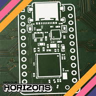
And here's the routing:

(TODO: silkscreen drawings :3)
I definitely struggled a little on the routing to not interfere with the ground fill, but almost all the traces are on the back while the fill is on the front. I just made the GPIO pins line up nicely with how the traces are able to be routed.
All in all, this didn't take too long but ended up being more complicated than I thought to make sure the connections line up properly.
It's hard to see, but the connectors are on the bottom of the PCB, like so:

Wiring
This new PCB does complicate wiring a little more, as the ESP is in no shape to power an LED matrix capable of pulling 4A. Instead, I followed Adafruit's advice and added a dedicated 5A power supply to the BOM, along with an adapter. This did unfortunately raise the price, but it won't work properly without these. The full details of the wiring for this is in the README.
CAD Updates
Since this PCB is quite a bit smaller than the Matrix Portal, the CAD had to be updated to reflect this. Luckily, it was very simple to just extrude to fill in the gap.

Conclusion
I hope this makes the project complicated enough to pass review. This project has been on my mind for months and it would be really cool to build it!
 Iamalive 🚀
requested changes for Flight Deck ago
Iamalive 🚀
requested changes for Flight Deck ago
Hey, at the moment this can be a tier 5 project at best. Is there a way you can use cheaper parts/add more complexity to justify a tier 4? Thanks!
MrDiamond
submitted Flight Deck for ship review ago
 PenguinMo
requested changes for Flight Deck ago
PenguinMo
requested changes for Flight Deck ago
It seems that there is no wiring diagram you can draw this or make it in tinkercad
MrDiamond
submitted Flight Deck for ship review ago
 technical_.
requested changes for Flight Deck ago
technical_.
requested changes for Flight Deck ago
Please make sure to include a wiring diagram, or something to show how you connected all of the electrical components together!
Its very hard to discern how everything is wired up.
MrDiamond
submitted Flight Deck for ship review ago
MrDiamond
added to the journal ago
CAD Finished!
Added the mounting holes! I had a couple screws laying around and measured those to get a gauge for how big I should make the holes. This should work well!
I almost placed them upside down without realizing, which wouldn't actually pose any issue with the hardware, just that it would be more unstable.

After double checking everything again, it should be ready for submission again!
MrDiamond
added to the journal ago
API and New Firmware!
Thank you reviewer for your feedback!
CAD
I still have work to do in the CAD model. I need to add holes for mounting, then it should be done. I'll finish that up tomorrow. Printing it is a different monster though.
This beast is about 330mm across, and only 21mm thick. Lucky for me, the diagonal of my build plate (256x256mm) ends up being ~362mm. Last time I checked, that's bigger than 330, and thus:

Yep. It somehow fits. Unfortunately, because of the way I had to stand it up...

This takes 8 hours and 1/4th of an entire spool, 1/4th of that going to just support unfortunately. I really don't want to split this thing up, it would complicate everything even further. A brim is totally necessary, I don't want to risk warping on the bottom or it just coming off the build plate.
Good thing Blueprint does filament reimbursement...
API + Firmware
The API was a struggle to find. There were a lot of requirements that I needed:
- Free
- LIVE data
- Can find flights in bounding box
- Good amount of information on found flights
- Reasonable limits (needs about 2 reqs/minute)
I finally found airlabs.co, which meets all the requirements. For some reason, the first time I signed up it put me on a waitlist so I emailed them, but it worked the second time around.
With this, I looked into some more actual firmware, and finished up what I could. The new firmware is in the repo.
Here's the code that fetches the necessary data from the API:

I am worried about the size of the response taking up too much RAM, as the full response looks like this:

And that's without any actual flight data. It's about 1.5kb, so we'll see how that plays out.
 zsharpminor ⚡
requested changes for Flight Deck ago
zsharpminor ⚡
requested changes for Flight Deck ago
This is a really cool project (as a flight enthusiast myself, I approve!), but I only have two requests - your firmware currently only displays "Hello World!" - is it possible to add a preliminary firmware segment showing which API(s) you're planning on calling and how you're planning on getting your data. This is mainly because your project has very little hardware and CAD complexity (it would be a tier 5 without the firmware). Additionally, please add some more complexity to your CAD and journal how you did it - even just simple mounting screws or a kickstand would be just fine, it's just to confirm your CAD design process! Finally, your LED matrix is 320mm in width, so make sure you have access to a printer with a 320-340mm bed (most are ~256-280mm), or detail how you're planning on splitting your part :)
MrDiamond
submitted Flight Deck for ship review ago
MrDiamond
added to the journal ago
Basic Firmware + Repo Setup, Waiting For Review
Project repo all set up for review!

I've set up some very basic firmware as well as read through a bunch of guides and information on the board and matrix.
I decided on using CircuitPython, as I'm tired of working in C. It is really frustrating sometimes, and I'm not a huge fan of Python but this seems a lot easier to get set up. I just want to focus on programming the actual product instead of trying to get the microcontroller to work for multiple hours on end.
This guide has been incredibly helpful, and I imagine it will be even more so when I actually program stuff.

I've also added a BOM, which came down to around $37, which I'm really proud of.
Anyway, it's time to submit for review and hopefully order some parts!
MrDiamond
added to the journal ago
The Plan, Basic CAD
Project #3!!


This one is a little bigger and firmware-based. Basically, I've seen a couple builds of an LED matrix that displays live flight data from flights near your location. I thought this was super interesting and a good thing to add to my room, since my house does lie on multiple flight paths.
Hardware
I've already picked out the hardware for this project! Only two items:
- 64x32 RGB LED Matrix, 5mm pitch, 320x160mm (I couldn't find a monochrome one)
- Adafruit Matrix Portal ESP-S3
The matrix is meant to plug into the Adafruit ESP, and then it's pretty simple from there.
I've already found the parts for cheap on Aliexpress, under $50 somehow. This project definitely falls in tier 4; it is relatively simple.
As you probably saw, the CAD is already mostly done. It was relatively simple but I have to consider how this is going to be mounted to the wall in addition to securely holding this massive display I'm using. Printing this will be a challenge, as it has to be diagonal and on its side to fit on my print bed.
Firmware
The firmware is a little more complex; it needs to get data from some API (preferably without payment), filter for the ones close enough, and display all the flight data on the matrix. Additionally, I would like customizable sleep times or some other fun things to display when there's no flights.
MrDiamond
started Flight Deck ago
1/2/2026 8 PM - The Plan, Basic CAD
Project #3!!
This one is a little bigger and firmware-based. Basically, I've seen a couple builds of an LED matrix that displays live flight data from flights near your location. I thought this was super interesting and a good thing to add to my room, since my house does lie on multiple flight paths.
Hardware
I've already picked out the hardware for this project! Only two items:
- 64x32 RGB LED Matrix, 5mm pitch, 320x160mm (I couldn't find a monochrome one)
- Adafruit Matrix Portal ESP-S3
The matrix is meant to plug into the Adafruit ESP, and then it's pretty simple from there.
I've already found the parts for cheap on Aliexpress, under $50 somehow. This project definitely falls in tier 4; it is relatively simple.
As you probably saw, the CAD is already mostly done. It was relatively simple but I have to consider how this is going to be mounted to the wall in addition to securely holding this massive display I'm using. Printing this will be a challenge, as it has to be diagonal and on its side to fit on my print bed.
Firmware
The firmware is a little more complex; it needs to get data from some API (preferably without payment), filter for the ones close enough, and display all the flight data on the matrix. Additionally, I would like customizable sleep times or some other fun things to display when there's no flights.
1/2/2026 9 PM - Basic Firmware + Repo Setup, Waiting For Review
Project repo all set up for review!
I've set up some very basic firmware as well as read through a bunch of guides and information on the board and matrix.
I decided on using CircuitPython, as I'm tired of working in C. It is really frustrating sometimes, and I'm not a huge fan of Python but this seems a lot easier to get set up. I just want to focus on programming the actual product instead of trying to get the microcontroller to work for multiple hours on end.
This guide has been incredibly helpful, and I imagine it will be even more so when I actually program stuff.
I've also added a BOM, which came down to around $37, which I'm really proud of.
Anyway, it's time to submit for review and hopefully order some parts!
1/4/2026 12 AM - API and New Firmware!
Thank you reviewer for your feedback!
CAD
I still have work to do in the CAD model. I need to add holes for mounting, then it should be done. I'll finish that up tomorrow. Printing it is a different monster though.
This beast is about 330mm across, and only 21mm thick. Lucky for me, the diagonal of my build plate (256x256mm) ends up being ~362mm. Last time I checked, that's bigger than 330, and thus:
Yep. It somehow fits. Unfortunately, because of the way I had to stand it up...
This takes 8 hours and 1/4th of an entire spool, 1/4th of that going to just support unfortunately. I really don't want to split this thing up, it would complicate everything even further. A brim is totally necessary, I don't want to risk warping on the bottom or it just coming off the build plate.
Good thing Blueprint does filament reimbursement...
API + Firmware
The API was a struggle to find. There were a lot of requirements that I needed:
- Free
- LIVE data
- Can find flights in bounding box
- Good amount of information on found flights
- Reasonable limits (needs about 2 reqs/minute)
I finally found airlabs.co, which meets all the requirements. For some reason, the first time I signed up it put me on a waitlist so I emailed them, but it worked the second time around.
With this, I looked into some more actual firmware, and finished up what I could. The new firmware is in the repo.
Here's the code that fetches the necessary data from the API:
I am worried about the size of the response taking up too much RAM, as the full response looks like this:
And that's without any actual flight data. It's about 1.5kb, so we'll see how that plays out.
1/4/2026 12 PM - CAD Finished!
Added the mounting holes! I had a couple screws laying around and measured those to get a gauge for how big I should make the holes. This should work well!
I almost placed them upside down without realizing, which wouldn't actually pose any issue with the hardware, just that it would be more unstable.
After double checking everything again, it should be ready for submission again!
1/12/2026 - Some Reworking (New PCB!)
Well, after some... discussion, I need to make the project more complex. Let's add a PCB!
The PCB
It ends up being very simple. All it needs to do is connect an ESP to a bunch of connector pins on the LED Matrix. The wiring diagram looks like this:
(The extra pins on the ESP are just in case of emergency jumper wires.)
And here's the routing:
(TODO: silkscreen drawings :3)
I definitely struggled a little on the routing to not interfere with the ground fill, but almost all the traces are on the back while the fill is on the front. I just made the GPIO pins line up nicely with how the traces are able to be routed.
All in all, this didn't take too long but ended up being more complicated than I thought to make sure the connections line up properly.
It's hard to see, but the connectors are on the bottom of the PCB, like so:
Wiring
This new PCB does complicate wiring a little more, as the ESP is in no shape to power an LED matrix capable of pulling 4A. Instead, I followed Adafruit's advice and added a dedicated 5A power supply to the BOM, along with an adapter. This did unfortunately raise the price, but it won't work properly without these. The full details of the wiring for this is in the README.
CAD Updates
Since this PCB is quite a bit smaller than the Matrix Portal, the CAD had to be updated to reflect this. Luckily, it was very simple to just extrude to fill in the gap.
Conclusion
I hope this makes the project complicated enough to pass review. This project has been on my mind for months and it would be really cool to build it!
1/13/2026 - Silkscreen Drawings, Price Optimization!
NOTE TO REVIEWER: I have optimized the price of some of the items to be cheaper than the listed funding request and cart image. Please look at the new BOM in the repo!
I've finally finished the PCB to its fullest, adding these wonderful silkscreen drawings to give it more character. Yes, I know you won't really see this PCB, but it's for fun.
Other than that, I've optimized the prices of everything!
Aliexpress has this neat little button that finds exact matches of the item in your cart that may be cheaper! I have replaced the terminal block adapters and power supply to knock around $8 off the project!
Other than that, just waiting on review!
2/2/2026 - It's here! It's finally here!!
Everything arrived all in one piece (individually) and all the parts are actually correct!
Firmware troubles
After getting everything soldered (and definitely not soldering the pin headers on the wrong side the first time), I loaded CircuitPython and attempted to run the code. Unfortunately, it did not work first try. Turns out, the dev board I chose doesn't support the rgbmatrix library I need.
After about 2 hours of google searching I decided to abandon CircuitPython for barebones Arduino/C++ code that I'm more experienced in. Luckily, there were two primary libraries to choose from: Adafruit Protomatter and some random guy's Adafruit GFX wrapper for HUB75 displays.
I tried both libraries, and the latter library worked, but for some reason, the green channel wasn't working, despite the pins being correct. Adafruit Protomatter ended up being very stubborn with what pins it uses.
After more tedious hours of figuring out pinout issues, I still don't understand what was wrong with Protomatter because nothing displayed, and there were no errors. The other library was working exactly correct, but I hadn't realized that I put the green channel pins on input-only GPIOs (why do these exist??????)
Anyway, after some emergency jumper wires (I added extra pin holes just for this), all the channels finally work and we have a real display!
Ok REAL firmware time!
Now that it actually works (the biggest hurdle with these kinds of projects), I can finally implement all the features!
To start, I added airline images that I had made some pixel art for, and got them onto the display!
I personally think this looks really good (and somehow my pixel art also looks good)!
Next up is getting the API working. I'm currently stuck on this step as the API can only receive HTTPS requests, which are a little harder to send then plain HTTP. There's not very good documentation for this stuff but I'll make a devlog when the API works.
After that, I'll make the home screen and the webserver to configure everything!