Solas Sense Shamrock Lamp
Im making a small lamp with rgb leds and ldr. if the room is bright so will the leds and if the room is dim so are the leds
Created by
 anadskman
Tier 4
5 views
0 followers
 CAN ⚡🚀
approved Solas Sense Shamrock Lamp ago
CAN ⚡🚀
approved Solas Sense Shamrock Lamp ago
Tickets awarded: 30 tickets
Tier: 4
Very cool!
anadskman
submitted Solas Sense Shamrock Lamp for ship review ago
 cubit010 ⚡
requested changes for Solas Sense Shamrock Lamp ago
cubit010 ⚡
requested changes for Solas Sense Shamrock Lamp ago
fixing paglu perma reject!
you should be good to resubmit now!
Tier: 4
anadskman
submitted Solas Sense Shamrock Lamp for ship review ago
anadskman
added to the journal ago
Soldered The PCB

I started with the leds, making sure the 5v pin is in the correct place and then i soldered the 4 pins and check with a multimeter that they weren't touching.

Then i soldered the resistors on, im glad i changed to through holes but it would of looked nice if i picked a slightly bigger footprint but its good how it is.
then I soldered the ldr and its resistor.

and the esp, i soldered the headers first then the board to the headers.
After i checked connectivity i looked at the schematic and realised my ldr was wired wrong, the gpio 0 is meant to be 3.3v so i just scratched the copper and ran a wire through.
I scratched the wrong line originally but i fixed it with a bit of solder and some scrap wire.

Then I powered and uploaded the frimware.
Lastly I Assembled into the 3d printed case and superglue it together

 samliu ⚡🚀
approved Solas Sense Shamrock Lamp ago
samliu ⚡🚀
approved Solas Sense Shamrock Lamp ago
Tier approved: 4
Grant approved: $33.00
This is great work and super cool! I'm excited to see how it'll turn out. Approved!
anadskman
submitted Solas Sense Shamrock Lamp for ship review ago
samliu ⚡🚀
requested changes for Solas Sense Shamrock Lamp ago
You're almost there, please make sure you include source files of your CAD. Check the submission guidelines (https://blueprint.hackclub.com/about/submission-guidelines).
anadskman
submitted Solas Sense Shamrock Lamp for ship review ago
 Tanuki ⚡🚀
requested changes for Solas Sense Shamrock Lamp ago
Tanuki ⚡🚀
requested changes for Solas Sense Shamrock Lamp ago
Good work! I would appreciate it if you used global labels, this was a bit hard to follow. Sorry I that I didnt comment on this earlier, DM me this project and ill review it fast since this was my fault. Also, can you please add the PCB to the BOM? Thanks! Nice shape tho!
anadskman
submitted Solas Sense Shamrock Lamp for ship review ago
 zsharpminor ⚡
requested changes for Solas Sense Shamrock Lamp ago
zsharpminor ⚡
requested changes for Solas Sense Shamrock Lamp ago
Hi, this is really cool, but you need a BOM.csv to be able to qualify for a grant, please read through submission guidelines and resubmit once you've got that! Thanks!
anadskman
submitted Solas Sense Shamrock Lamp for ship review ago
anadskman
added to the journal ago
Fixed mising gpio connection
I forgot to wire my Light Dependent Resistor to pin 2 so i had to updated the schematic and pcb.
Then i uploaded the new kicad files to my github page.

Tanuki ⚡🚀
requested changes for Solas Sense Shamrock Lamp ago
Hey! Your light pentiometer isn't wired correctly I believe. I think there should be another gpio sensor that can sense it, can you sanity check please? I think it should look like this: https://electrocredible.com/wp-content/uploads/2024/01/LDR-PICO-W-SCHEMATIC.webp
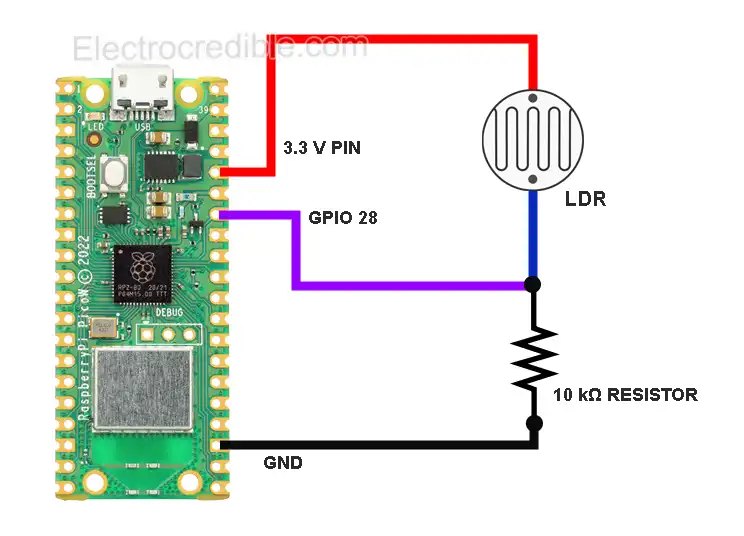
anadskman
submitted Solas Sense Shamrock Lamp for ship review ago
anadskman
added to the journal ago
Fixed PCB, Finished Cad, Made BOM/Github
I change the resistors to a bigger size.
Afterwards I downloaded the pcb as a step file and uploaded to fusion 360,
then I traced around the pcb a size bigger to make the case.
Lastly I Made up the BOM and Github.


anadskman
added to the journal ago
Made the Schematic, Routed PCB, Started CAD
I started by adding esp32-c3 supermini, 3 resistors per 1 rgb led, ldr + resistor.
I wired everything, assigned footprints, and Then I made up the pcb.
I had to make the edge.cuts design in fusion 360, export as step and convert into dxf and then... add to edge.cuts.
Lastly I place and routed everything.


anadskman
started Solas Sense Shamrock Lamp ago
1/6/2026 - Made the Schematic, Routed PCB, Started CAD
I started by adding esp32-c3 supermini, 3 resistors per 1 rgb led, ldr + resistor.
I wired everything, assigned footprints, and Then I made up the pcb.
I had to make the edge.cuts design in fusion 360, export as step and convert into dxf and then... add to edge.cuts.
Lastly I place and routed everything.
1/9/2026 - Fixed PCB, Finished Cad, Made BOM/Github
I change the resistors to a bigger size.
Afterwards I downloaded the pcb as a step file and uploaded to fusion 360,
then I traced around the pcb a size bigger to make the case.
Lastly I Made up the BOM and Github.
1/15/2026 - Fixed mising gpio connection
I forgot to wire my Light Dependent Resistor to pin 2 so i had to updated the schematic and pcb.
Then i uploaded the new kicad files to my github page.
3/29/2026 - Soldered The PCB
I started with the leds, making sure the 5v pin is in the correct place and then i soldered the 4 pins and check with a multimeter that they weren't touching.
Then i soldered the resistors on, im glad i changed to through holes but it would of looked nice if i picked a slightly bigger footprint but its good how it is.
then I soldered the ldr and its resistor.
and the esp, i soldered the headers first then the board to the headers.
After i checked connectivity i looked at the schematic and realised my ldr was wired wrong, the gpio 0 is meant to be 3.3v so i just scratched the copper and ran a wire through.
I scratched the wrong line originally but i fixed it with a bit of solder and some scrap wire.
Then I powered and uploaded the frimware.
Lastly I Assembled into the 3d printed case and superglue it together