Desk Robot
Small Desk Robot to keep me company and aid in my procrastination. Visually inspired by the small droid in Andor
Created by
 The Geek
Tier 3
68 views
2 followers
 PriXy
gave kudos to Desk Robot ago
PriXy
gave kudos to Desk Robot ago
Amongus
 1mon ⚡
approved Desk Robot ago
1mon ⚡
approved Desk Robot ago
Tickets awarded: 264 tickets
Tier: 3
really impressive project!
1mon ⚡
submitted Desk Robot for ship review ago
The Geek
submitted Desk Robot for ship review ago
 nok
gave kudos to Desk Robot ago
nok
gave kudos to Desk Robot ago
wow this is really cool! the ui can be more polished :) nice work!
1mon ⚡
requested changes for Desk Robot ago
really awesome job on the project, the paint is so clean and it just looks so nice!! id like to see some info in your readme about how to set up the firmware for this project, it can be really short! additionally. please upload a picture of the completed project to the readme so others can see it! please read through https://blueprint.hackclub.com/about/submission-guidelines to make sure you are good to resubmit!
Tier: 3
 Tanuki ⚡🚀
submitted Desk Robot for ship review ago
Tanuki ⚡🚀
submitted Desk Robot for ship review ago
The Geek
submitted Desk Robot for ship review ago
 PenguinMo
requested changes for Desk Robot ago
PenguinMo
requested changes for Desk Robot ago
Wow this is looking really cool
The Geek
submitted Desk Robot for ship review ago
The Geek
added to the journal ago
Finished the Project
I have now Soldered and inserted the components into the Desk Robot case and he is ready for use to keep me company during studying. I think sorting the wires and fitting in everything was more difficult than expected and I swapped out the plastic geared servos with metal ones as I found them when I was unpacking my soldering iron and figured they would be more reliable.
This project has been very fun, slightly frustrating at times but overall very enjoyable. I think there are improvements I could make if I made a V2 like bearings, perhaps tactile buttons and maybe a larger screen. That being said here is the final product competed on the corner of my laptop at my desk. 

The Geek
added to the journal ago
Coding
Next I did some coding to add the OLED and adjust the UI so each servo can move to the full extent at the same moment. The new UI looks like this:

The code I changed will be on the GitHub repo when that gets made as it will probably get changed a couple times before I am fully happy with it.I had some issues with the OLED and it all kind of broke all of it but I got it working after a couple tries with the OLED on different pins.
The Geek
added to the journal ago
Post Processing the Print
I spent a couple hours post processing the print today as it didn't come out too clean but I think it has turned out fine now after sanding and priming and finally a couple coats of paint.
I also soldered the OLED that arrived today but I will cover that later.


Next I will be adding the screen into the code and adding some interesting things for it to do to keep me company
The Geek
added to the journal ago
Updated UI
So today I updated the UI to be more intuitive. Before this update the control for the Servos was 2 individual sliders - really annoying to use. And now it is a joystick with re-centering and after a couple issues with the range of motion, it works reasonably well.

The Geek
added to the journal ago
Modeling the case
Next I started modelling the case. For this I will be using Fusion 360 and publicly available models for the electronic components. For this I have used:
https://grabcad.com/library/mg90s-dimension-reference-measured-1
https://grabcad.com/library/oled-0-91-128x32-1
https://grabcad.com/library/mc-esp32-c3-super-mini-black-pink-red-1
I then modelled this so that it had two pivots and the screen:

It has the port on the back and I'll add silicon feet to the bottom.
Next I'm going to print this off and do some coding.
The Geek
added to the journal ago
Designing the Case
I took a quick break from coding and decided to design the case. I did some sketches before pulling out the isometric paper and rendered this before requiring CAD later.

Yes I intend for silly faces to be included
The Geek
added to the journal ago
Wiring and Coding
Next was my Pain.
I started wiring up the servos and ESP32 C3 (The OLED display is still in the mail) and figuring out how I was best to control these servos.
Connecting to my home WIFI with both my phone and the ESP device - 4hrs:
While this seemed like a great idea to me to proved to have a lot of issues and resulted in me spending about 4 hours on this method only to dump it. I first encountered general problems and had to code up the device following a "Random Nerd Tutorials" Tutorial with a web controlled servo but this took a while adjusting the code for the C3 device where frankly I don't think it should have and if I was better wouldn't have taken much time at all. This was down to the hardware differences and how the boards send signals - I think.
In the end I just about managed to hook up the 2 servos and managed to wirelessly control them from my phone (Actually was my laptop but shhhhhh). Unfortunately, after reloading the ESP it stopped working due to - as I later found out - the IP address changes each time. After learning about this I spent much time trying to set up a permanent IP address for the device but had no success.
Connecting to the ESP32 C3's WIFI - 2hrs:
This to me seemed like a decent idea and I was able to adjust the code with some help to run this but long story short it ended up being very very unreliable and at no point did I manage to get the servos to move with my phone constantly disconnecting from the WIFI and not wanting to reconnect as it wasn't providing an internet connection unlike my juicy home internet connected WIFI. Unfortunately, I also wasted time thinking it was the web interface and attempting to auto-launch the interface but at no point did that work and so I cut my losses.
BLE - 2hrs:
At this point I went back to researching controlling the ESP and BLE came up as a viable option. After messing up with the RF controller app which was very confusing and getting movement once I had hope for this method. I managed to update the code to work - again with help - and managed to connect to the servos via Bluetooth from my phone which was honestly such a great feeling. This method was especially great as it still allowed my phone to be used and apparently the power fluctuations are not as bad.
Next I will be designing the case and I will be looking into improving the user interface as currently it is just two slider and this is difficult to use.

Current code:
#include <Arduino.h>

#include <ESP32Servo.h>

#include <BLEDevice.h>

#include <BLEServer.h>

#include <BLEUtils.h>

// ---- SERVO OBJECTS ----

Servo servo1;

Servo servo2;

// ---- SERVO GPIO PINS (ESP32-C3 SAFE) ----

static const int SERVO1_PIN = 2;

static const int SERVO2_PIN = 4;

// ---- BLE UUIDs (MUST MATCH WEB UI) ----

#define SERVICE_UUID        "12345678-1234-1234-1234-1234567890ab"

#define SERVO1_CHAR_UUID   "12345678-1234-1234-1234-1234567890ac"

#define SERVO2_CHAR_UUID   "12345678-1234-1234-1234-1234567890ad"

// ---- BLE CALLBACK CLASS ----

class ServoCallback : public BLECharacteristicCallbacks {

  void onWrite(BLECharacteristic* characteristic) override {

    String value = characteristic->getValue();

    if (value.length() == 0) return;

    int angle = constrain(value.toInt(), 0, 180);

    if (characteristic->getUUID().toString() == SERVO1_CHAR_UUID) {

      servo1.write(angle);

      Serial.print("Servo 1 -> ");

      Serial.println(angle);

    }

    if (characteristic->getUUID().toString() == SERVO2_CHAR_UUID) {

      servo2.write(angle);

      Serial.print("Servo 2 -> ");

      Serial.println(angle);

    }

  }

};

void setup() {

  Serial.begin(115200);

  delay(1000);

  // ---- SERVO SETUP ----

  servo1.setPeriodHertz(50);

  servo2.setPeriodHertz(50);

  servo1.attach(SERVO1_PIN, 500, 2400);

  servo2.attach(SERVO2_PIN, 500, 2400);

  servo1.write(90);

  servo2.write(90);

  // ---- BLE SETUP ----

  BLEDevice::init("ESP32-C3-Servos");   // Name shown in browser

  BLEServer* server = BLEDevice::createServer();

  BLEService* service = server->createService(SERVICE_UUID);

  BLECharacteristic* servo1Char = service->createCharacteristic(

    SERVO1_CHAR_UUID,

    BLECharacteristic::PROPERTY_WRITE

  );

  BLECharacteristic* servo2Char = service->createCharacteristic(

    SERVO2_CHAR_UUID,

    BLECharacteristic::PROPERTY_WRITE

  );

  servo1Char->setCallbacks(new ServoCallback());

  servo2Char->setCallbacks(new ServoCallback());

  service->start();

  BLEAdvertising* advertising = BLEDevice::getAdvertising();

  advertising->addServiceUUID(SERVICE_UUID);

  advertising->setScanResponse(true);

  advertising->start();

  Serial.println("BLE ready for Web Bluetooth");
void loop() {

  // Nothing needed here

}
The Geek
added to the journal ago
Working out the hardware
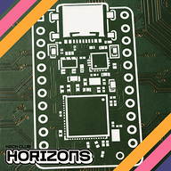
To begin I decided to determine how the project would work and jump right in as I had a free weekend at the end of the Christmas period. I have decided to use:
- ESP32 C3 module
- MG90 Servos (Plastic)
- 0.91" OLED Display
- Buttons
I will be using the C3 module as it allows for wireless access and control from my phone. I can also code this via the Arduino IDE and so it shouldn't be too difficult - fingers crossed.
I am going to be using two servos to provide some lifelike movement to the robot in a way to add physical responses to stimulations. I have managed to create a mock up of the wiring needed but for now will focus on the servos and learning the different controlling methods via wifeless stuff.

The Geek
added to the journal ago
Started the project
I started this project with a little bit of brainstorming and sketches for what this project could look like and perhaps do. This is my first projects where I will be creating everything from the ground up so it probably wont be too complicated but this will be a big step for me and sounds very fun.

The Geek
started Desk Robot ago
1/6/2026 8:15 PM - Started the project
I started this project with a little bit of brainstorming and sketches for what this project could look like and perhaps do. This is my first projects where I will be creating everything from the ground up so it probably wont be too complicated but this will be a big step for me and sounds very fun.
1/6/2026 8:36 PM - Working out the hardware
To begin I decided to determine how the project would work and jump right in as I had a free weekend at the end of the Christmas period. I have decided to use:
- ESP32 C3 module
- MG90 Servos (Plastic)
- 0.91" OLED Display
- Buttons
I will be using the C3 module as it allows for wireless access and control from my phone. I can also code this via the Arduino IDE and so it shouldn't be too difficult - fingers crossed.
I am going to be using two servos to provide some lifelike movement to the robot in a way to add physical responses to stimulations. I have managed to create a mock up of the wiring needed but for now will focus on the servos and learning the different controlling methods via wifeless stuff.
1/6/2026 9:01 PM - Wiring and Coding
Next was my Pain.
I started wiring up the servos and ESP32 C3 (The OLED display is still in the mail) and figuring out how I was best to control these servos.
Connecting to my home WIFI with both my phone and the ESP device - 4hrs:
While this seemed like a great idea to me to proved to have a lot of issues and resulted in me spending about 4 hours on this method only to dump it. I first encountered general problems and had to code up the device following a "Random Nerd Tutorials" Tutorial with a web controlled servo but this took a while adjusting the code for the C3 device where frankly I don't think it should have and if I was better wouldn't have taken much time at all. This was down to the hardware differences and how the boards send signals - I think.
In the end I just about managed to hook up the 2 servos and managed to wirelessly control them from my phone (Actually was my laptop but shhhhhh). Unfortunately, after reloading the ESP it stopped working due to - as I later found out - the IP address changes each time. After learning about this I spent much time trying to set up a permanent IP address for the device but had no success.
Connecting to the ESP32 C3's WIFI - 2hrs:
This to me seemed like a decent idea and I was able to adjust the code with some help to run this but long story short it ended up being very very unreliable and at no point did I manage to get the servos to move with my phone constantly disconnecting from the WIFI and not wanting to reconnect as it wasn't providing an internet connection unlike my juicy home internet connected WIFI. Unfortunately, I also wasted time thinking it was the web interface and attempting to auto-launch the interface but at no point did that work and so I cut my losses.
BLE - 2hrs:
At this point I went back to researching controlling the ESP and BLE came up as a viable option. After messing up with the RF controller app which was very confusing and getting movement once I had hope for this method. I managed to update the code to work - again with help - and managed to connect to the servos via Bluetooth from my phone which was honestly such a great feeling. This method was especially great as it still allowed my phone to be used and apparently the power fluctuations are not as bad.
Next I will be designing the case and I will be looking into improving the user interface as currently it is just two slider and this is difficult to use.
Current code:
#include <Arduino.h>

#include <ESP32Servo.h>

#include <BLEDevice.h>

#include <BLEServer.h>

#include <BLEUtils.h>

// ---- SERVO OBJECTS ----

Servo servo1;

Servo servo2;

// ---- SERVO GPIO PINS (ESP32-C3 SAFE) ----

static const int SERVO1_PIN = 2;

static const int SERVO2_PIN = 4;

// ---- BLE UUIDs (MUST MATCH WEB UI) ----

#define SERVICE_UUID        "12345678-1234-1234-1234-1234567890ab"

#define SERVO1_CHAR_UUID   "12345678-1234-1234-1234-1234567890ac"

#define SERVO2_CHAR_UUID   "12345678-1234-1234-1234-1234567890ad"

// ---- BLE CALLBACK CLASS ----

class ServoCallback : public BLECharacteristicCallbacks {

  void onWrite(BLECharacteristic* characteristic) override {

    String value = characteristic->getValue();

    if (value.length() == 0) return;

    int angle = constrain(value.toInt(), 0, 180);

    if (characteristic->getUUID().toString() == SERVO1_CHAR_UUID) {

      servo1.write(angle);

      Serial.print("Servo 1 -> ");

      Serial.println(angle);

    }

    if (characteristic->getUUID().toString() == SERVO2_CHAR_UUID) {

      servo2.write(angle);

      Serial.print("Servo 2 -> ");

      Serial.println(angle);

    }

  }

};

void setup() {

  Serial.begin(115200);

  delay(1000);

  // ---- SERVO SETUP ----

  servo1.setPeriodHertz(50);

  servo2.setPeriodHertz(50);

  servo1.attach(SERVO1_PIN, 500, 2400);

  servo2.attach(SERVO2_PIN, 500, 2400);

  servo1.write(90);

  servo2.write(90);

  // ---- BLE SETUP ----

  BLEDevice::init("ESP32-C3-Servos");   // Name shown in browser

  BLEServer* server = BLEDevice::createServer();

  BLEService* service = server->createService(SERVICE_UUID);

  BLECharacteristic* servo1Char = service->createCharacteristic(

    SERVO1_CHAR_UUID,

    BLECharacteristic::PROPERTY_WRITE

  );

  BLECharacteristic* servo2Char = service->createCharacteristic(

    SERVO2_CHAR_UUID,

    BLECharacteristic::PROPERTY_WRITE

  );

  servo1Char->setCallbacks(new ServoCallback());

  servo2Char->setCallbacks(new ServoCallback());

  service->start();

  BLEAdvertising* advertising = BLEDevice::getAdvertising();

  advertising->addServiceUUID(SERVICE_UUID);

  advertising->setScanResponse(true);

  advertising->start();

  Serial.println("BLE ready for Web Bluetooth");
void loop() {

  // Nothing needed here

}
1/6/2026 9:03 PM - Designing the Case
I took a quick break from coding and decided to design the case. I did some sketches before pulling out the isometric paper and rendered this before requiring CAD later.
Yes I intend for silly faces to be included
1/7/2026 - Modeling the case
Next I started modelling the case. For this I will be using Fusion 360 and publicly available models for the electronic components. For this I have used:
https://grabcad.com/library/mg90s-dimension-reference-measured-1
https://grabcad.com/library/oled-0-91-128x32-1
https://grabcad.com/library/mc-esp32-c3-super-mini-black-pink-red-1
I then modelled this so that it had two pivots and the screen:
It has the port on the back and I'll add silicon feet to the bottom.
Next I'm going to print this off and do some coding.
1/8/2026 - Updated UI
So today I updated the UI to be more intuitive. Before this update the control for the Servos was 2 individual sliders - really annoying to use. And now it is a joystick with re-centering and after a couple issues with the range of motion, it works reasonably well.
1/9/2026 - Post Processing the Print
I spent a couple hours post processing the print today as it didn't come out too clean but I think it has turned out fine now after sanding and priming and finally a couple coats of paint.
I also soldered the OLED that arrived today but I will cover that later.
Next I will be adding the screen into the code and adding some interesting things for it to do to keep me company
1/10/2026 9 PM - Coding
Next I did some coding to add the OLED and adjust the UI so each servo can move to the full extent at the same moment. The new UI looks like this:
The code I changed will be on the GitHub repo when that gets made as it will probably get changed a couple times before I am fully happy with it.I had some issues with the OLED and it all kind of broke all of it but I got it working after a couple tries with the OLED on different pins.
1/10/2026 11 PM - Finished the Project
I have now Soldered and inserted the components into the Desk Robot case and he is ready for use to keep me company during studying. I think sorting the wires and fitting in everything was more difficult than expected and I swapped out the plastic geared servos with metal ones as I found them when I was unpacking my soldering iron and figured they would be more reliable.
This project has been very fun, slightly frustrating at times but overall very enjoyable. I think there are improvements I could make if I made a V2 like bearings, perhaps tactile buttons and maybe a larger screen. That being said here is the final product competed on the corner of my laptop at my desk.