Hacker Key Guide
Make your own Hacker key!
Guide made by @smartlinuxcoder
Hey! Want to make your own 2FA key but have absolutely no clue where to start? You found the right place! In this tutorial, we’re going to make an rp2040 board as an example.
Designing your PCB
For this guide we’re going to be using Easyeda Pro, because it’s pretty easy, and I used it for my own project.
Start by opening up Easyeda Pro, make a new project, and open the Schematic “part” in the left menu
This should open up a new window with your schematic editor! Once you’re in, press the Shift-F keys on your keyboard. This should open up a menu where you can add components!
Search for the following to add them:
- RP2040 (LCSC Part#:C2040) (This will be our main processor!)
- W25Q128JVSIQ (LCSC Part#:C97521) (This will be our non-volatile memory chip!)
- X322512MSB4SI (LCSC Part#:C9002)
Start by placing these symbols down. They don’t have to be in any particular order.
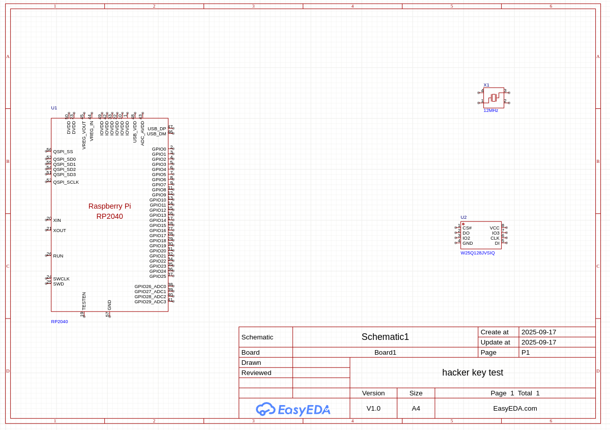
alt
^^ it should look something like this
Now it’s time to start wiring. Hit the Alt-W key on your keyboard to start wiring! This should make a green wire appear.
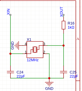
Here is how I wired the oscillator, and you may be wondering what are those other symbols I haven’t talked about.
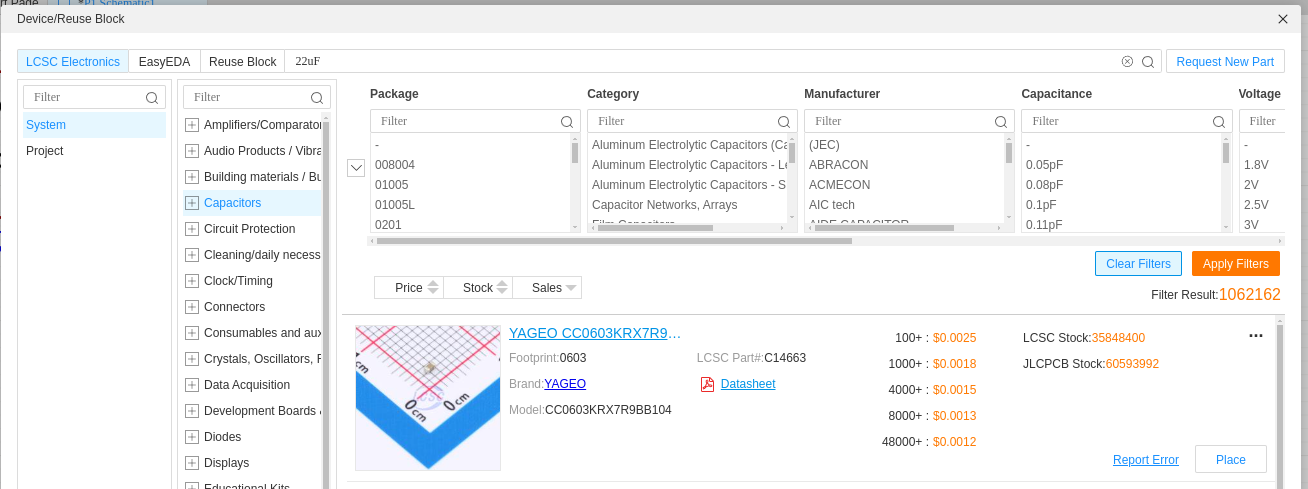
The other symbols (XIN, XOUT, and GND) are “Labels”. They act as virtual wires, connecting all points that share the same label name. This is to avoid making our schematic a spider web.the components that have C + a number as the name are Capacitors, to add them, just look for the value (in this case 22uF) and filter for “Capacitors”.
The ones that have a R + a number are Resistors, you can look for them in a similar manner
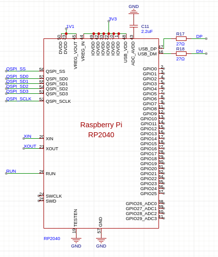
So, now time to wire the RP2040 chip
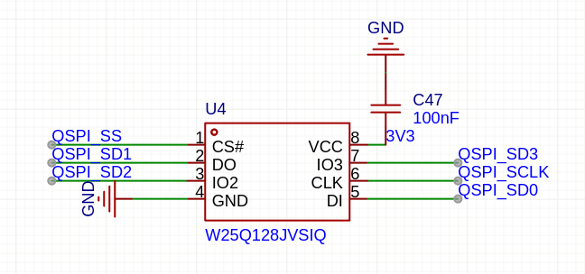
Time to do the same with the flash chip
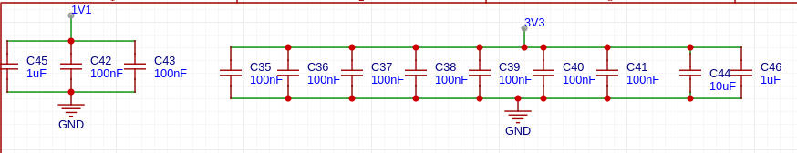
Next, add some decoupling capacitors, these should be enough:
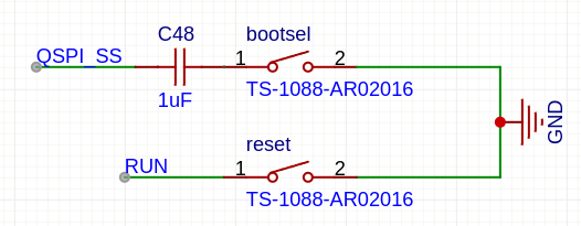
I also added some buttons (I used C720477 ones)
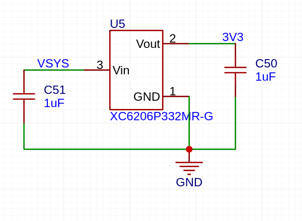
We also need a voltage regulator and a usb socket or a plug
I chose the XC6206P332MR-G as the regulator and wired it like so:
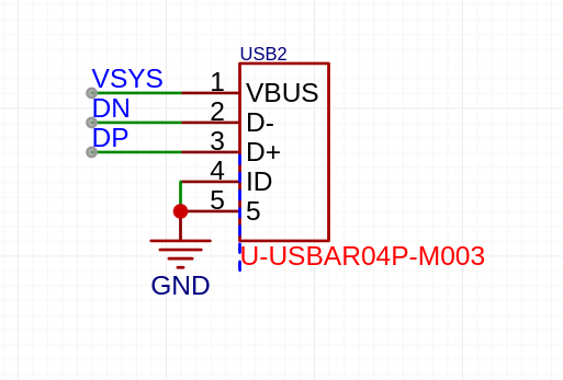
I chose to add a Usb Male for my pcb, so I found one and placed it, wired it like this:
Now that we’ve done the basics, do your part!
Add some LEDs, a screen?, mechanical switches?, a temperature sensor?
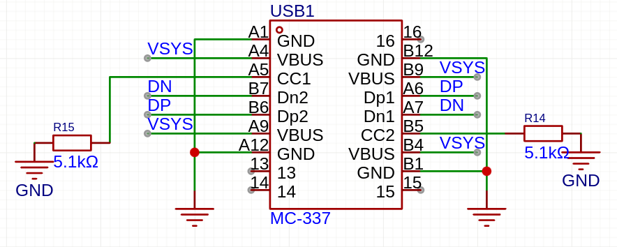
Bonus part: add USB-c
I wanted to add a usb-c male port to my board, so I wired it like a normal usb, I just added 2x5.1K resistors (to tell the other device we’re plugging in that this is a certain kind of device)
Once all the components are connected, we can start routing the actual PCB!
Routing the PCB
Great job on finishing the schematic! Hit the PCB1 button from the left menu to open the PCB editor:
Hit the “Import changes from schematic” button in the top menu, under Design. This will bring in all your parts!
Click anywhere on your screen to move your components
Now, we just need to make sure to place our chip and the decoupling capacitors we chose earlier next to eachother, same as the oscillator and the flash chip
To wire things up, click Alt-W, choose a pad with blue lines going out of it, and connect it to the other highlighted pad
If you’re just starting out PCB routing, I highly suggest you to follow this guide, as it still applies to this project: https://jams.hackclub.com/batch/usb-hub/part-2
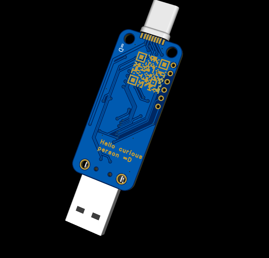
Now Here’s my finished design!
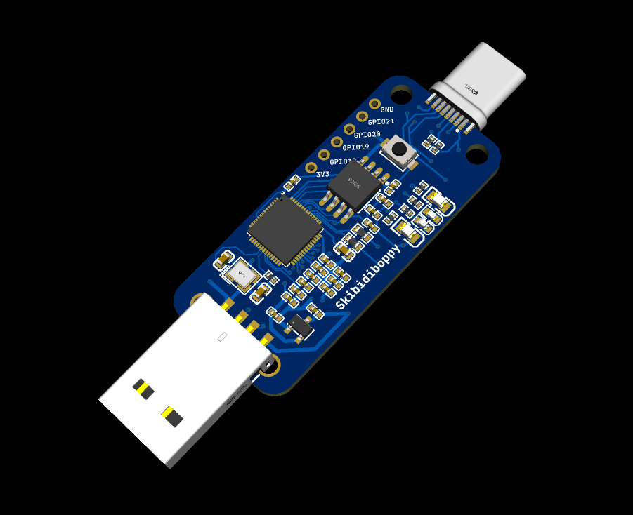
I added 4 LEDs, double USB connectors, and pads to expose GPIO pins!
I also added some holes for the case, and some nice rounded edges.I also added some “art” in the back of it!