Filament Recycler
Converting Bambu poop back into filament by using a screw based extruder. I want this to be small enough to be kept on top of a desk but do everything from shredding to edtruding and finally spooling
Created by
 Arnav Purbiya
No Grant
23 views
1 follower
Timeline
Arnav Purbiya
added to the journal ago
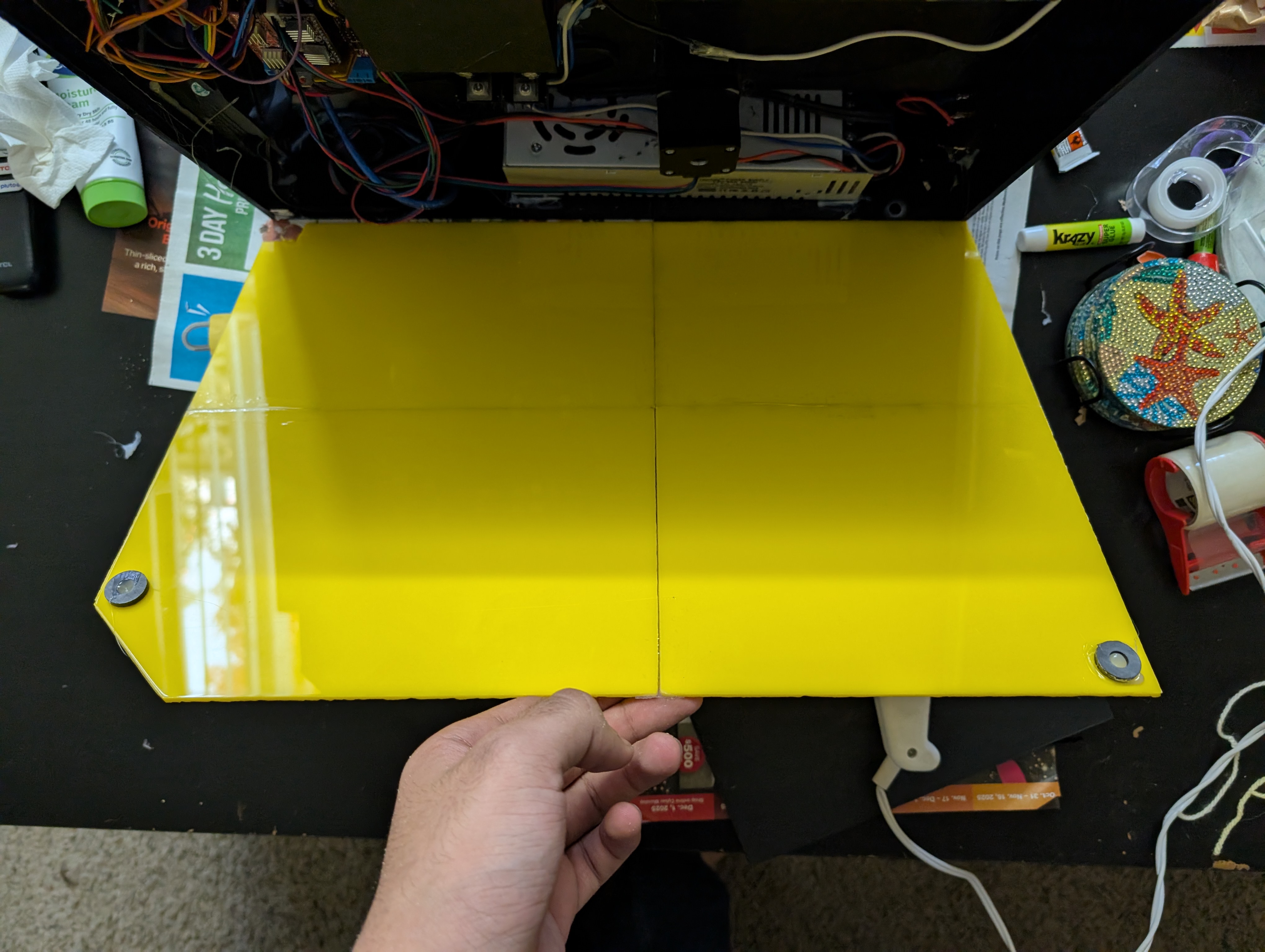
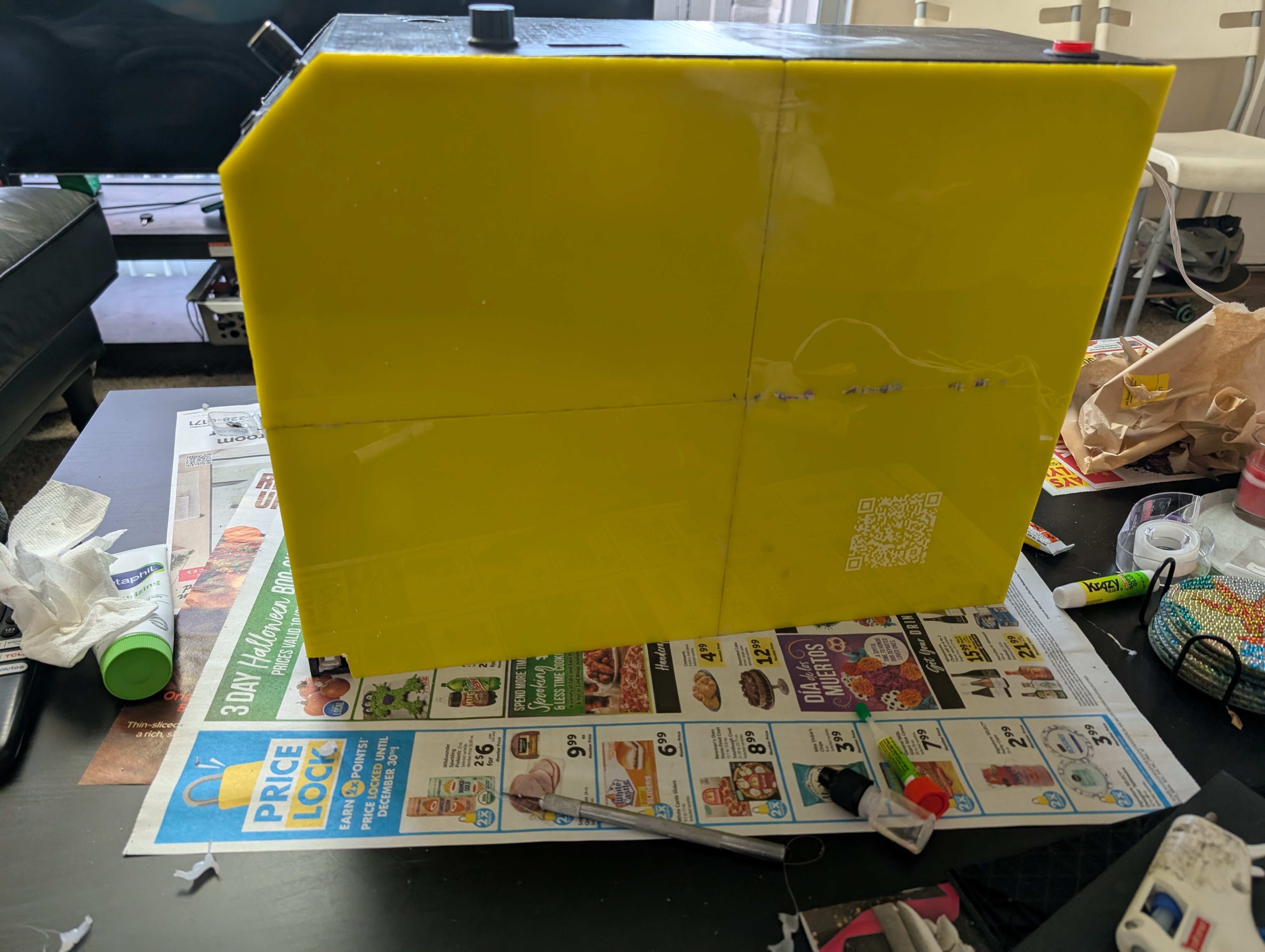
Laser Cutting + Assembly
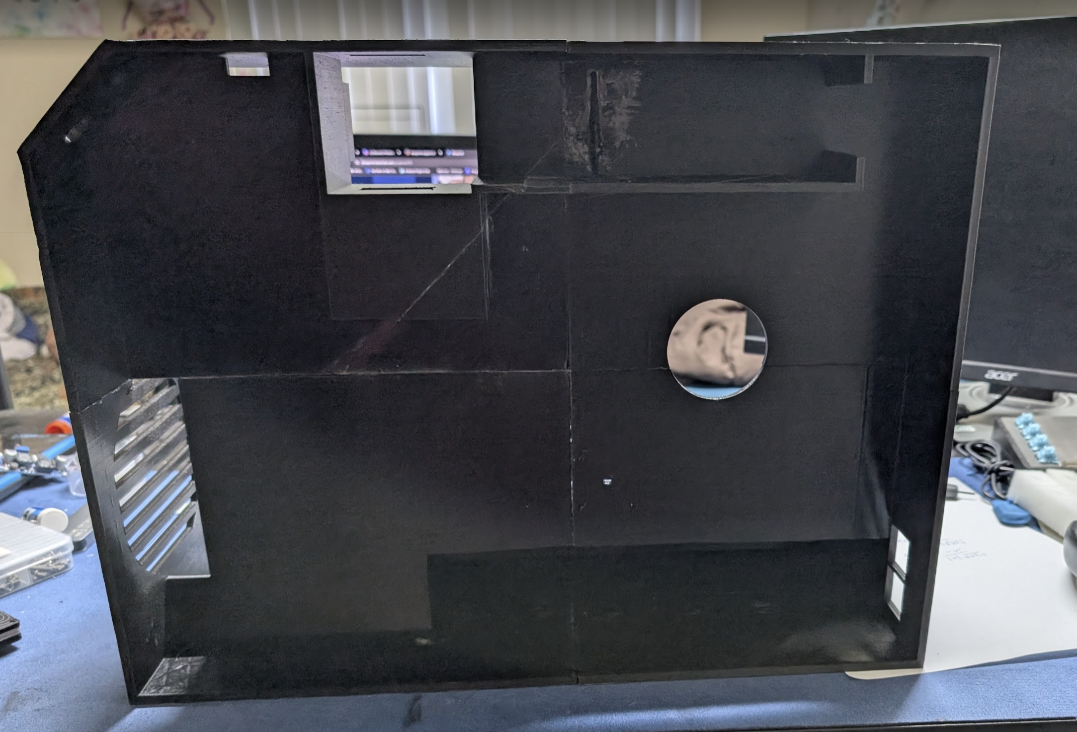
I had the dxf files ready so in school I got the panels ready for cutting. I wanted to used yellow acrylic for the back and clear for the front, turns out that clear doesn't cut well on the H2D somy teacher gave me a hacksaw I got to work. As for the yellow that was super easy and was able to cut it off.I also used a deburring tool to smooth out some of the edges. Then at home I started by pealing the sheets, for some reason on the yellow the film came off really easily almost in one piece, on the clear it just wasn't working and I wanted to get everything off. Since I used the hacksaw on the clear the cuts wern't straight so glueing it was a strugle I got super glue all over my hands and had to resort to using tape. After all 8 pannels were joined I got some magnets to hold the plates up. It doesn't look the best but it looks as good as I could with the technologies I had available to me. I have excluded all times that the laser was running and only included time I working hands on.
Arnav Purbiya
added to the journal ago
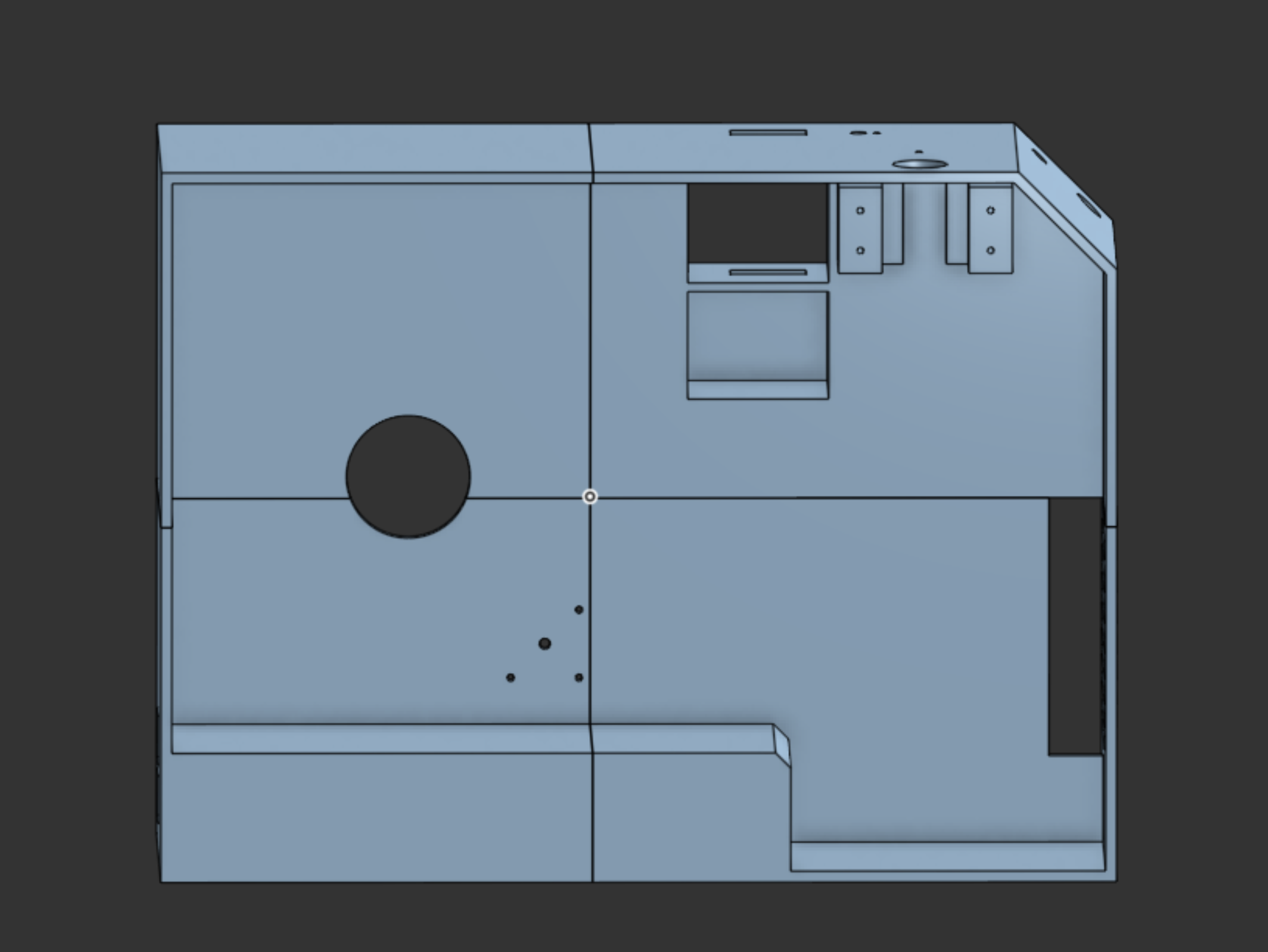
Sketching for laser
I want to make panels for the front and back of my project so its fully enclosed. To do that took the original skecth and copied it into a new sketch where I made a few changes of removing the lines and adding a spot for the usb printer cable. I am going to use magnets to attach everything together.
Since the H2D laser volume is small I split the sketch into 4 parts.
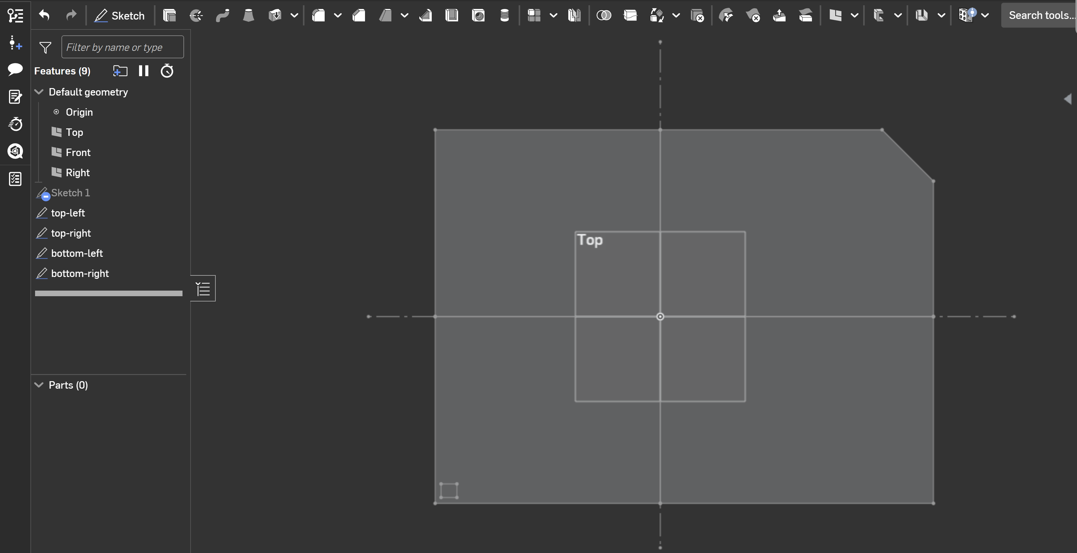
I will prep the laser cutter later today when I generate the paths in bambu suite I also want to add 2 qr codes that lead to the git hub and onshape. I am thinking about cutting the back panel out of wood and the front panel out of some sort of acrylic
Arnav Purbiya
added to the journal ago
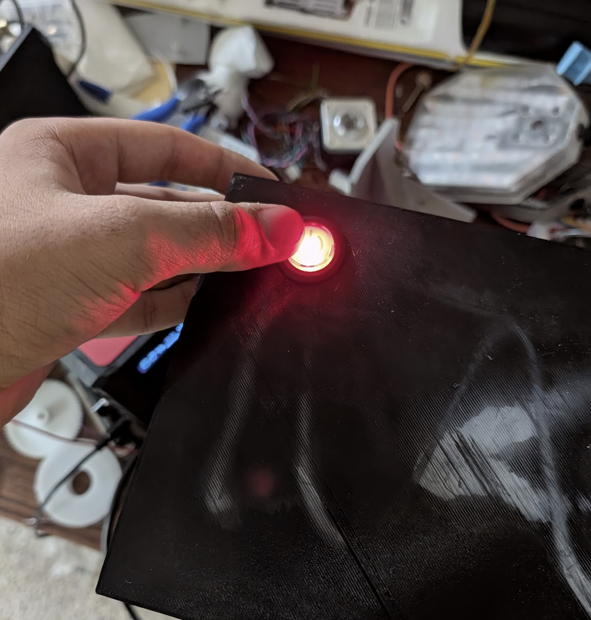
Fixing the shredder motor
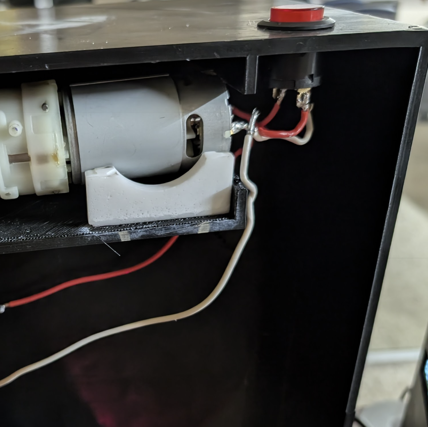
Well the fuse came, I replaced it and tested it only to find out the controller is now broken. :( No worries I had a back up plan, I had a button that I was originaly going to use instead of the controller. But unfortunalely I did not plan in my cad for a hole for the button. So I started heating up a screwdriver on the stove and then poking holes in a circle until I could knock out the center and have a hol big enough for the button. Then I soldered some wiers to the motor and the button to make that part of the cuircit work. Once that was working I started testing things like the spooler motor only to find out the pin nums in my code were wrong so I fixed that by looking up the actual pin nums on the ramps documentation and then I realized my max speed was too slow so I increased that as well. I am very close to test this entire thing, I just need something to cover the back and close the front.
Arnav Purbiya
added to the journal ago
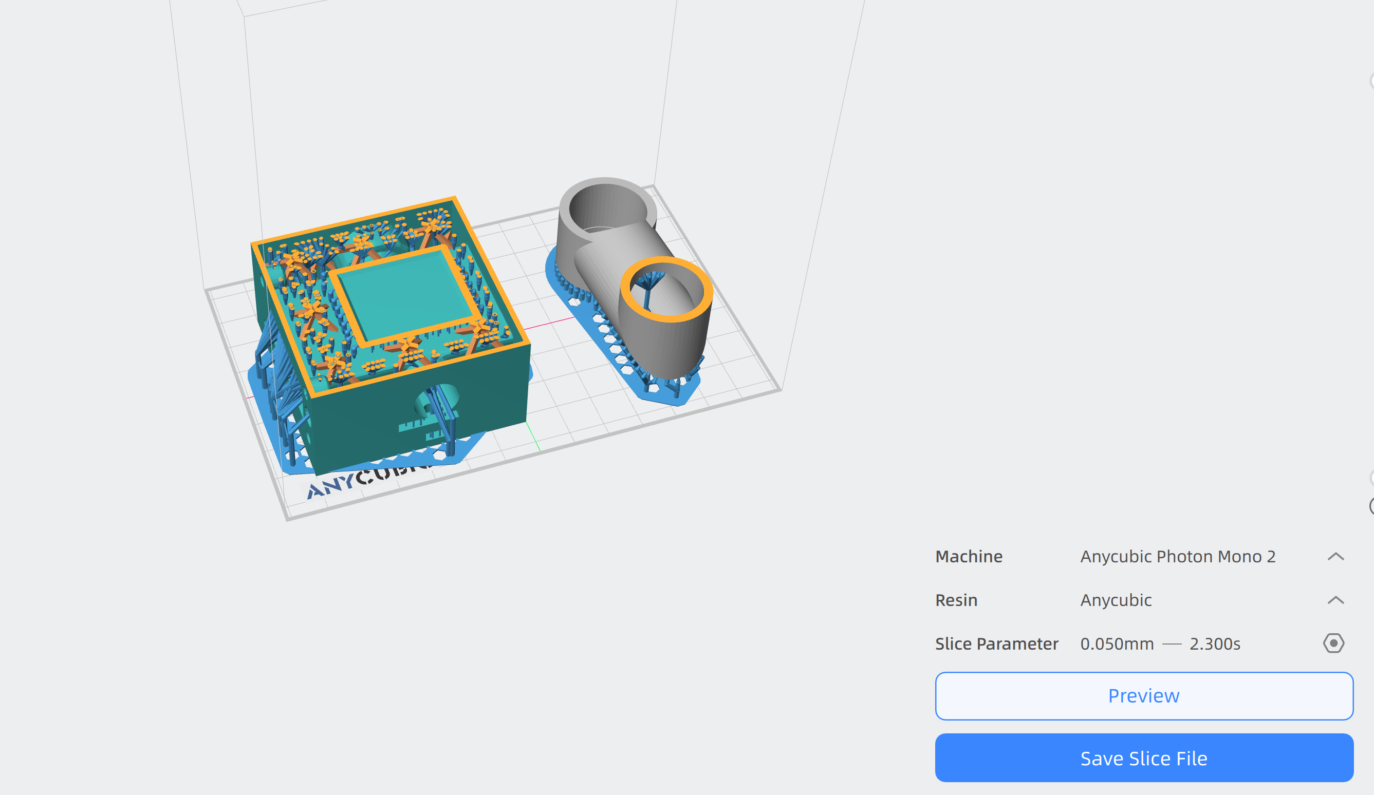
Print Clean up, Assembly and Electronics
I got a whole lot done today, after slicing the parts this morning I was able to start the prints, once the prints were done I got it off the plate cleaned it up. For assembly I got all the printed parts in, the spooler gear and the stepper motor, the shredder trey, the extruder pipe, and even the shredder motor mount. After doing all of this I had to fix the relay. I made a second custom relay module and got it put into the frame and wiered up. Soldering was hard as such a awkward angle. Once I got that done I tested to make sure the fans were running, they were working. I wanted to fix the vibrational motor as it seems to be vibrating too fast. I tried swaping it for a smaller motor but it is not helping, so I need to think of something better. I also did a full heating and cooling test getting the extruder to 300deg c. it took almost 25min to get to that temp, I think the power supply or the ramps board are not powerfull enought but I have to deal with it now. I am almost ready to do my first extrusion just need to get the new fuse and put it in and then run the shredder.
Arnav Purbiya
added to the journal ago
Early morning CAD
I woke up early today so I decided to get some cad done so I can print it later today. I increased the hole diameter of the motor gear and I designed a holder for the motor since it needs to be elevated a little. I have sliced both the models and will start the print in school today
Arnav Purbiya
added to the journal ago
Print clean up and code
So today the prints were done, so I got them off the build plate cleaned of all the glue from the build plates, cleaned off the prints by removing all supports and the rafts and brims and skirts. I have not tried assembling any of the parts other than the gear for the motor and the hole is too small so I will add that on the list of things to fix in CAD. Since I had all the wiring done I wanted to write some code to test all the components. I first traced every wire to make sure nothing we going to short or anything like that. Then with all the pin numbers I started writing the code. Here is what the code does, the rotary encoder controls the speed of the stepper motor, the button on the encoder toggles which motor speed it controls. The button toggles heating on or off. The fan relay turns on when heating and the vibrator turns on when extruder screw is spinning. Everything works except the relay module for the 2 fans, I think the relay is broken cause the light turns on when high but I don't hear a click. I will have to replace it with a custom diy relay like the other one. I have not tried heating yet but I will do that tomorrow. IN the code the hardest part was the logic for the toggle motor speed and figuring out a naming convention for all the different parts.
https://github.com/APurbiya/DIY_Recycler/commit/f3e4fef83a198f3a0e7130261d2be380f6635ba6
Arnav Purbiya
added to the journal ago
Print and finish wiring
Today I started by slicing everthing that I haven't already printed, then I started the print. When I checked on it in an hour 1 of the prints was going fine the other did not. So I purged the nozzel and cleaned it with come cold pulls and then restarted the print.
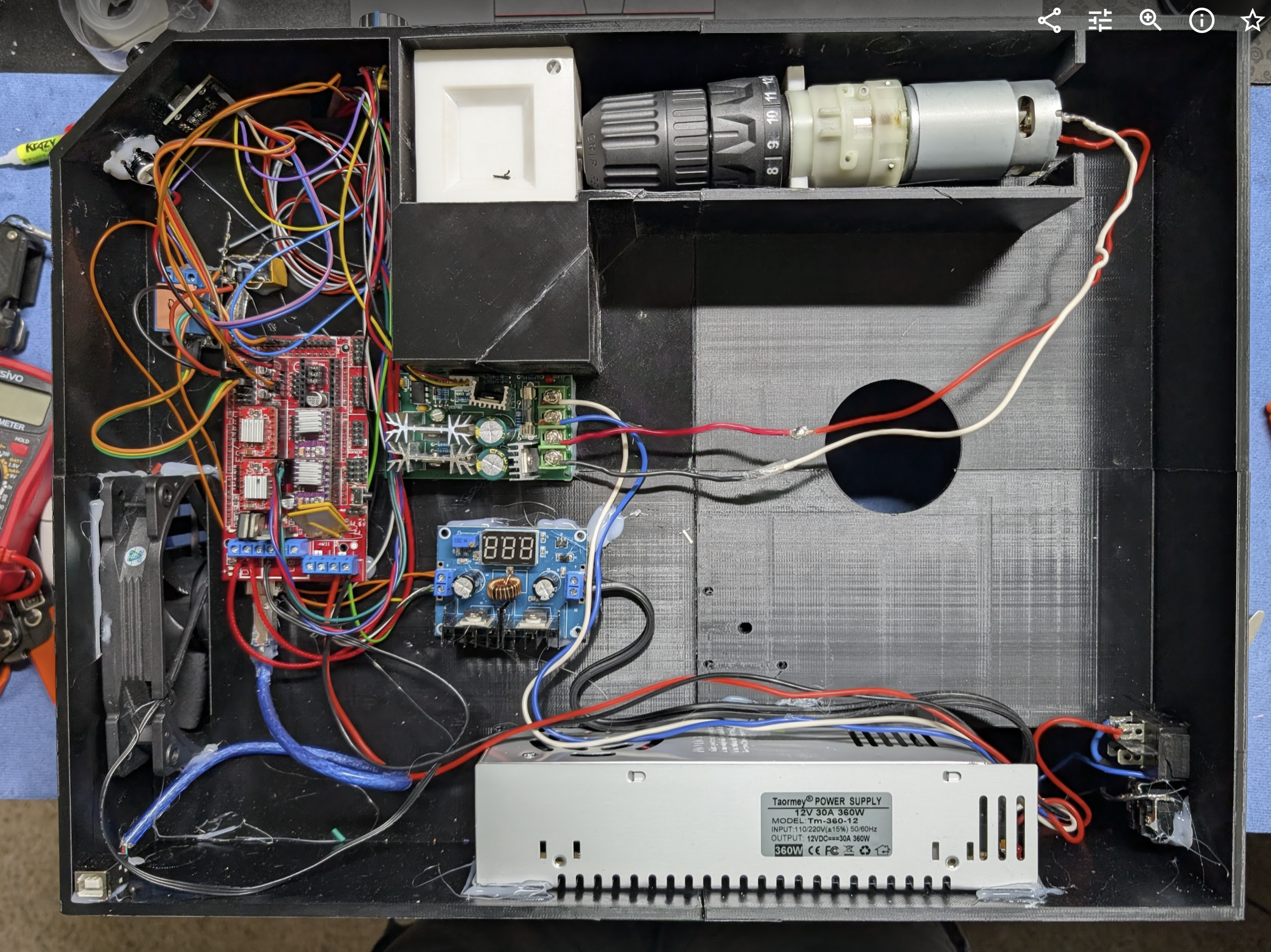
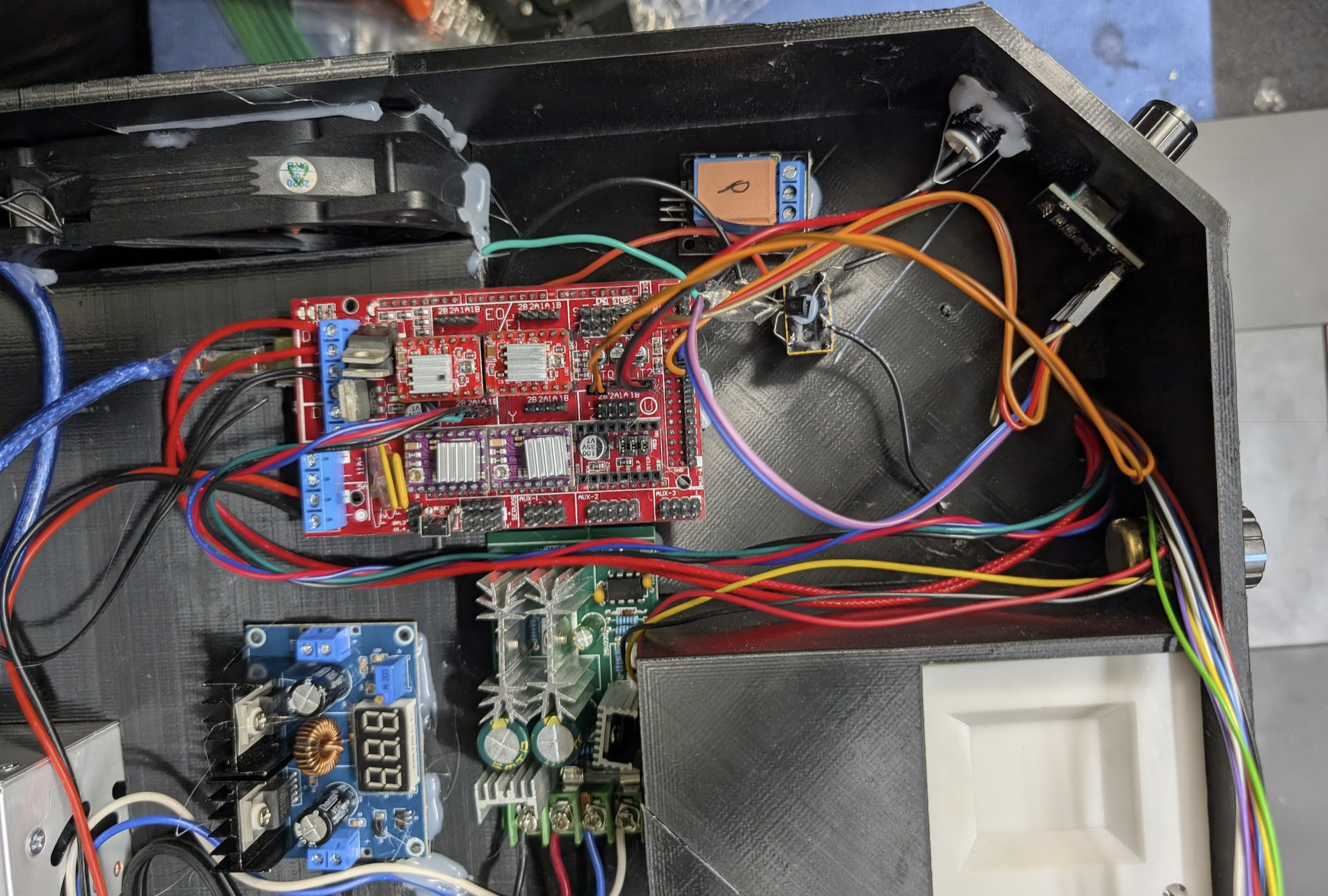
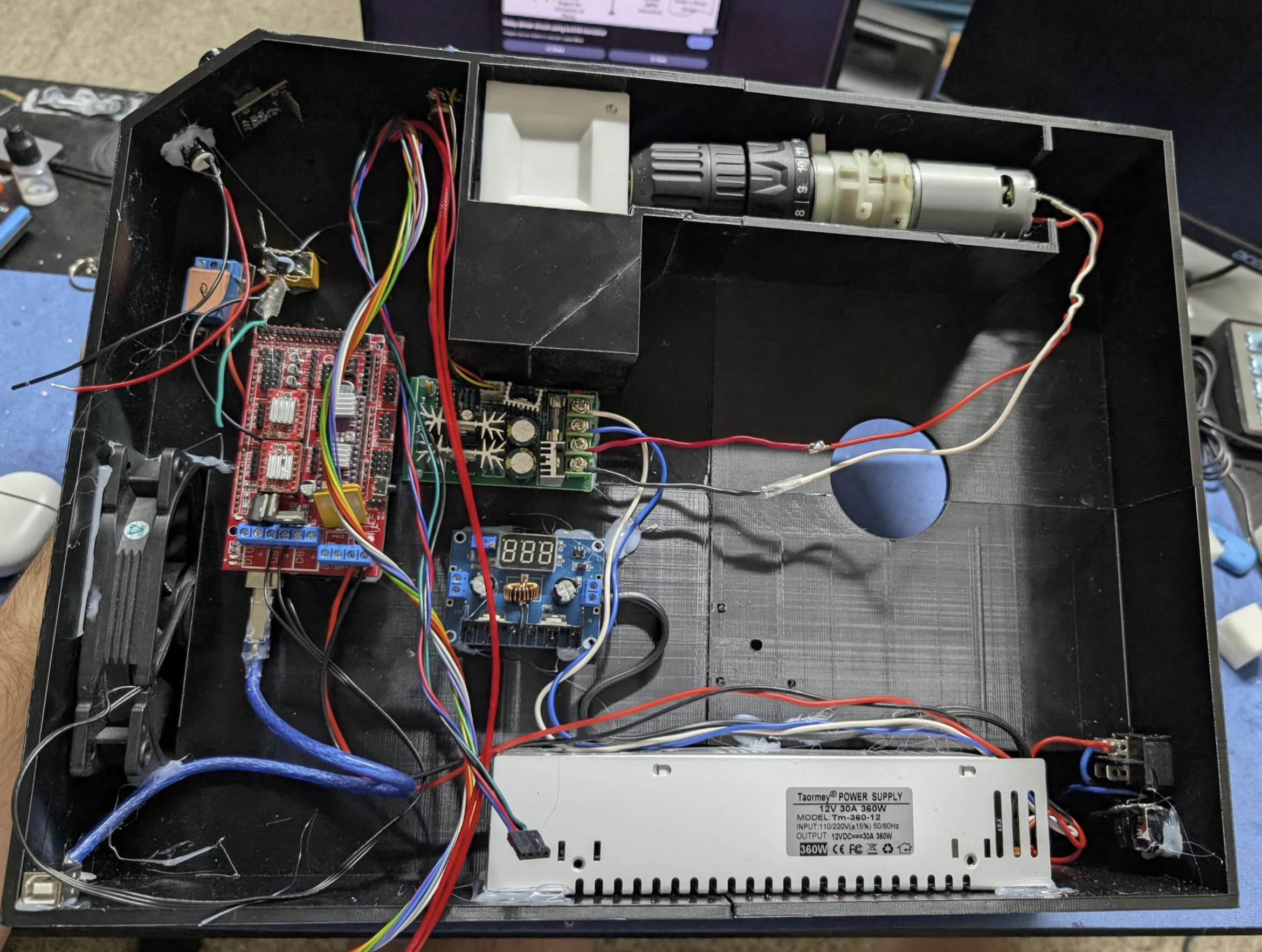
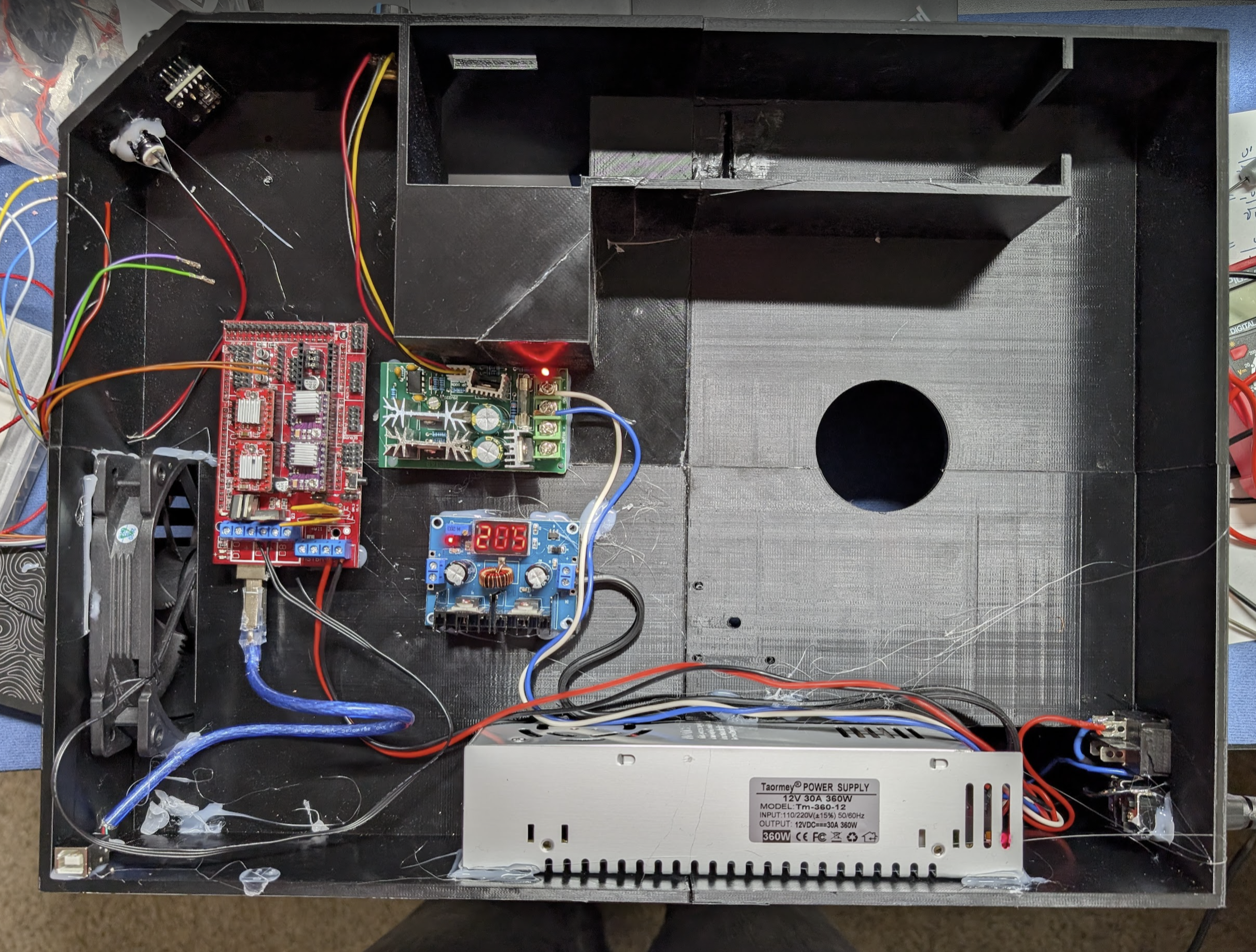
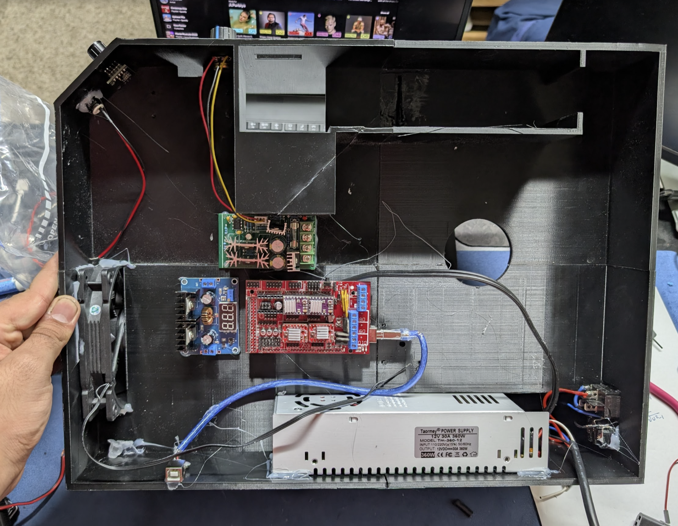
I also worked on finishing all the wiering from yesterday, I tried to keep everything clean for de bugging later on. I was able to wire the relays to the RAMPS board and the fans and motor to the relays and the buck. I had to Dupont crimp a few more wiers and like always that was a pain to do. one of these days I will get it.
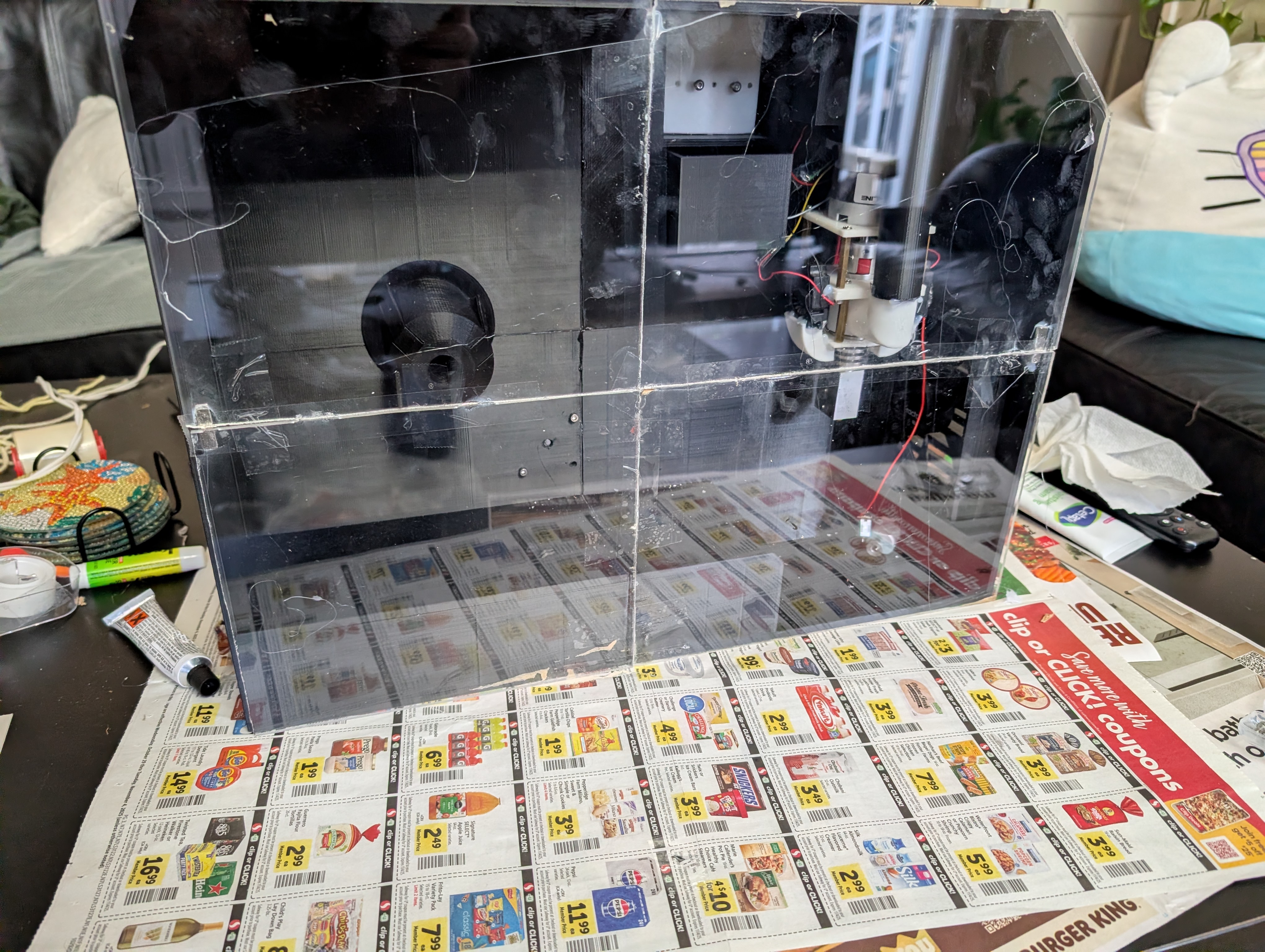
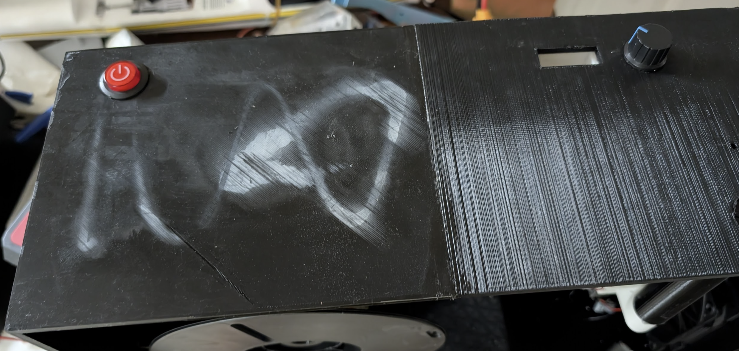
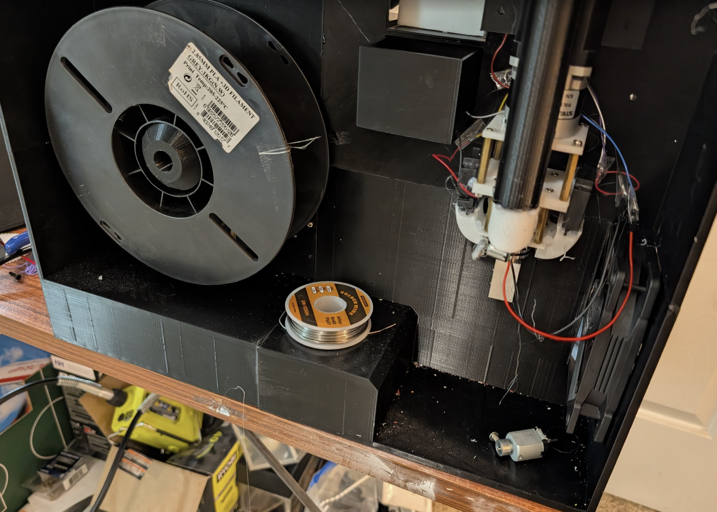
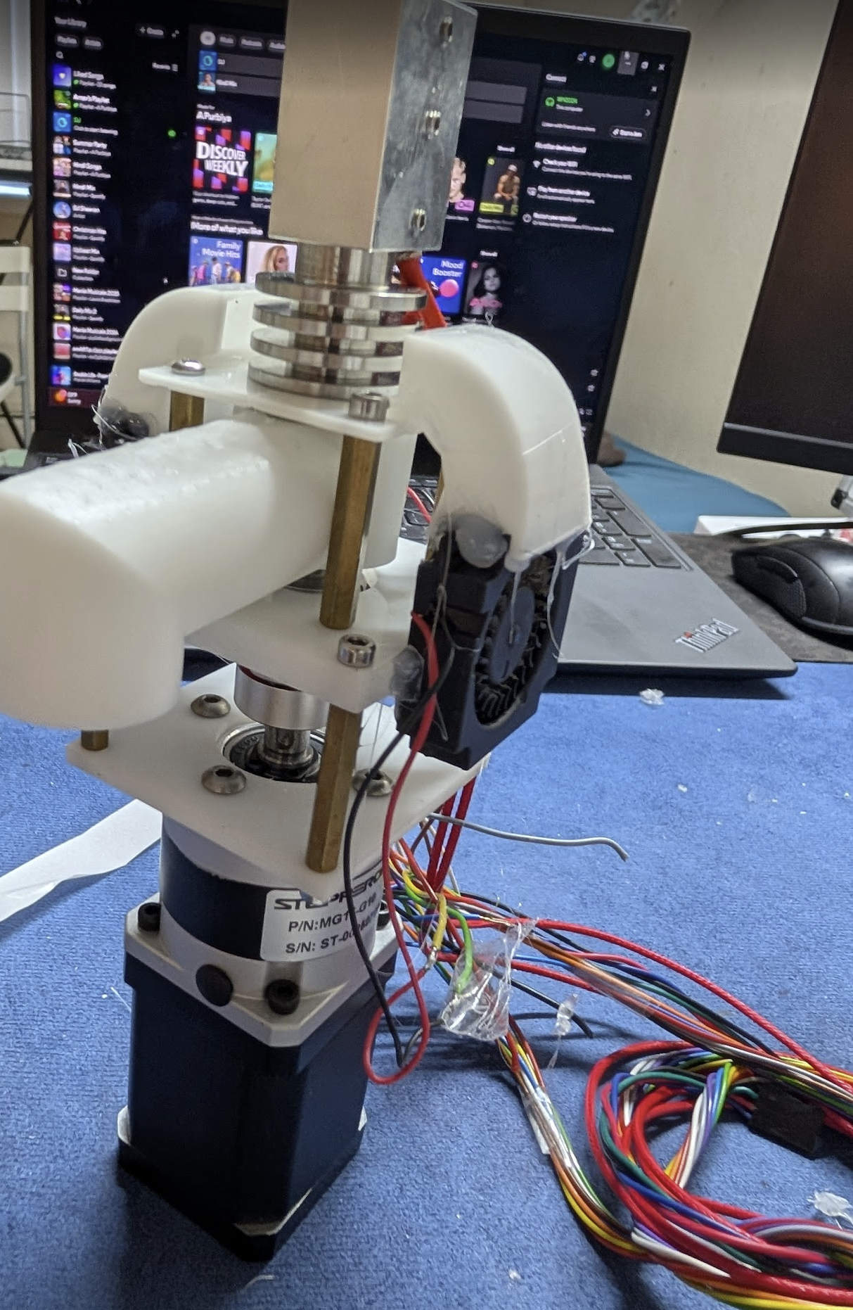
THis is what the final thing looks for now. I am going to check everything first tomorrow and then write code and test everything.
Arnav Purbiya
added to the journal ago
Started Wiring
I got a bunch of the wires criped and pluged in! Criping DuPont is not fun but I am working on getting better. So far I got the frist stepper motor, heater, 12v fan, button, temp sensor and rotory encoder all wired up. As I am doing this I am trying to keep all the wires as tidy as I can so trouble shooting later on is easy. I still need a wire the relays and the fans and motor. All the componets I still need to do run on 5v from the buck thats why I am doing that later.
Arnav Purbiya
added to the journal ago
CAD Changes
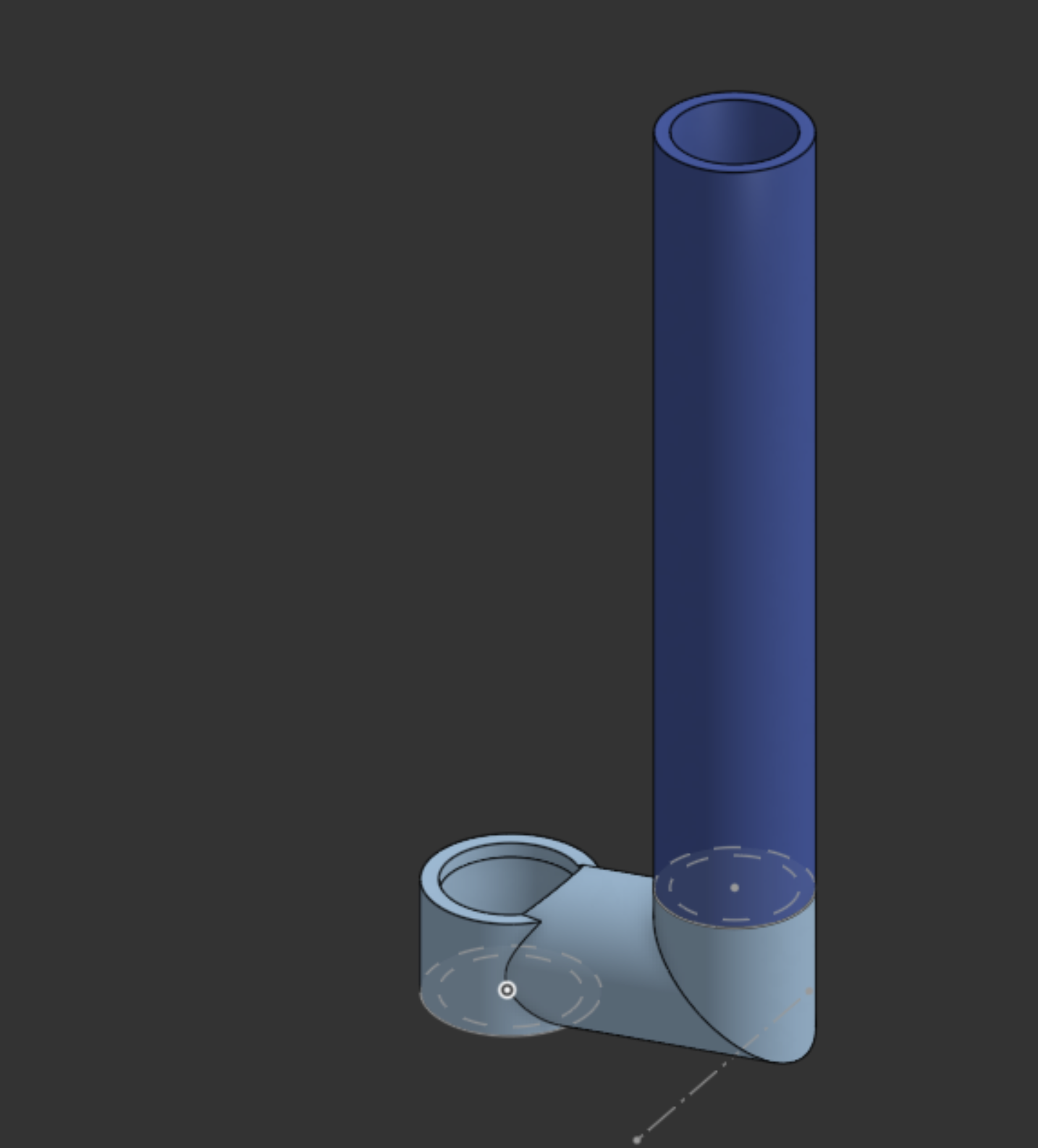
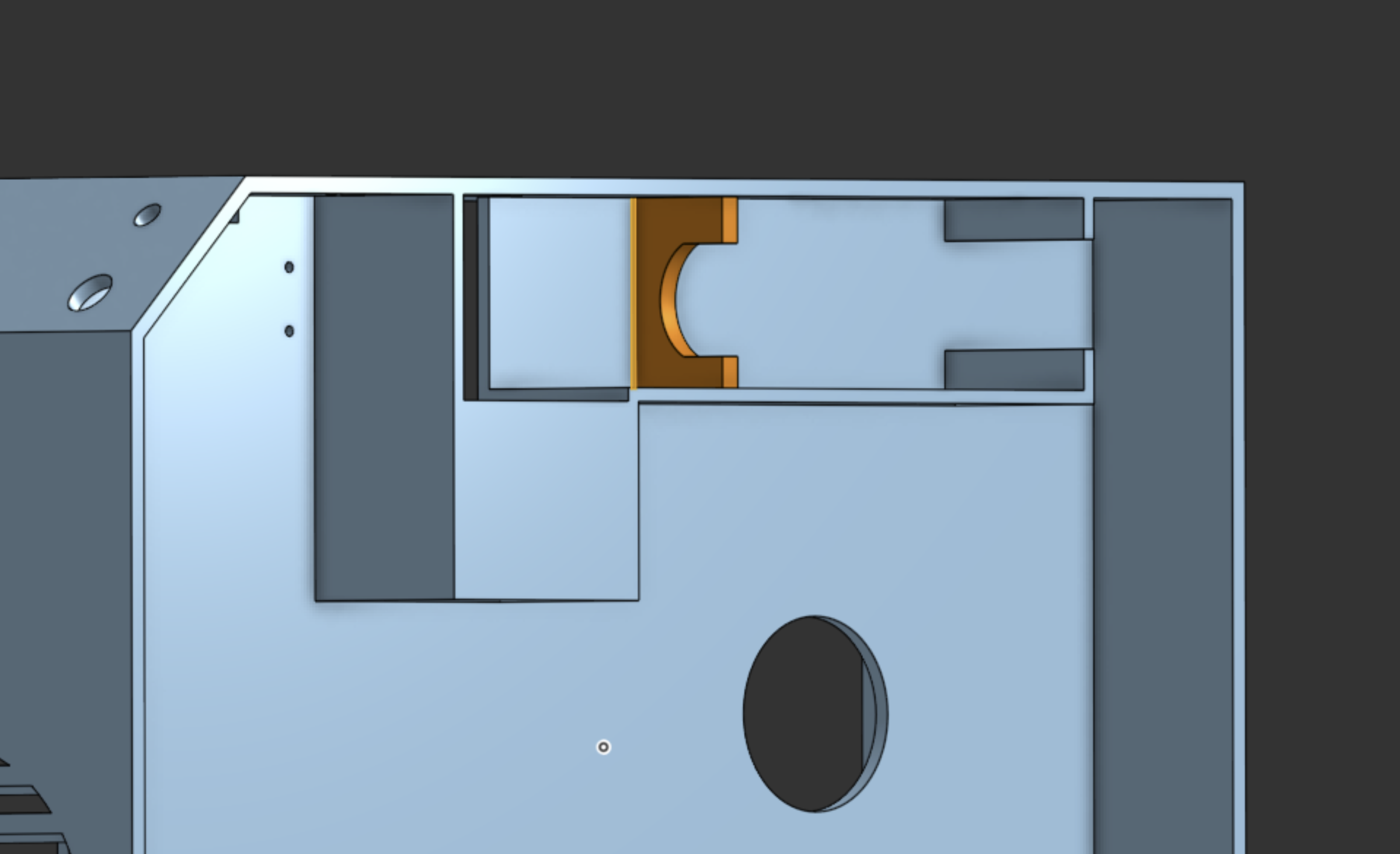
Since I realized that the motor count currently doesn't work I fixed it in cad to slot in and hopefully not let the motor spin anymore. I also fixed the pipe that connects to the chute because It was rally thick and the ID was not very big. I have sliced these prints and will start the print later today.
Arnav Purbiya
added to the journal ago
I popped a fuse :(
While testing the shredder, I put some of the filamanet scraps in the top and turned on the motor that all got scredded fine, but then I increased the speed and put some more, this is when the motor came out of the mount and started spinning the body and the fuse on the motor controler popped. I found and order some replacements but now in the mean time I need to do some more cad work to fix all this. I has to untangle all the wiers and clean up all the mess as well from this giant mess up :(
Arnav Purbiya
added to the journal ago
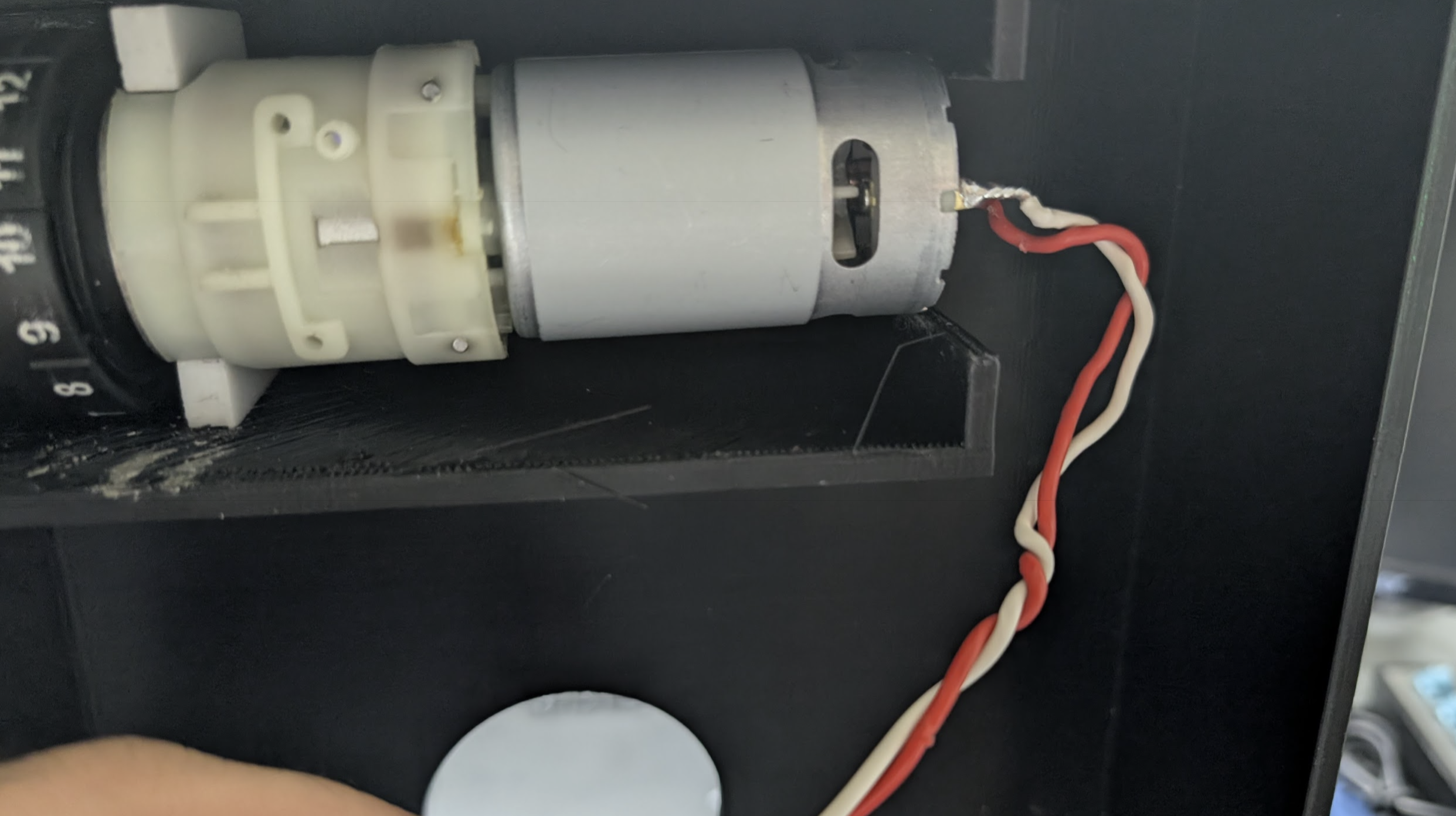
Shredder + Motor Assembeled
Yesterday I had cleaned up the shredder print so today I started getting it put into the main frame. I started by curring the ruler with the dremel so it is the correct length to go into the print. I got the drill gear box screwed in and then I could slide the whole thing in. This is when I realized that the print had not tolerance so I had to sand the thing untill it fit. This took really long since I had cured the resin. I also had to solder longer wiers to the motor but they wern't long enough so I solder some more wier to that. After it fit in I noticed I might have made a small mistake with the motor mounnt. It does not go all the way to the top so I think the motor might spin. While I was pack there I also glued in 2 relays, one of them was just a relay module the other one I had to custom make by looking up the scematics there was no clear way to do this so it took a lot of research and talking to Chat GPT. But I got it done. Next I am going to test the shredder with some poop.
Arnav Purbiya
added to the journal ago
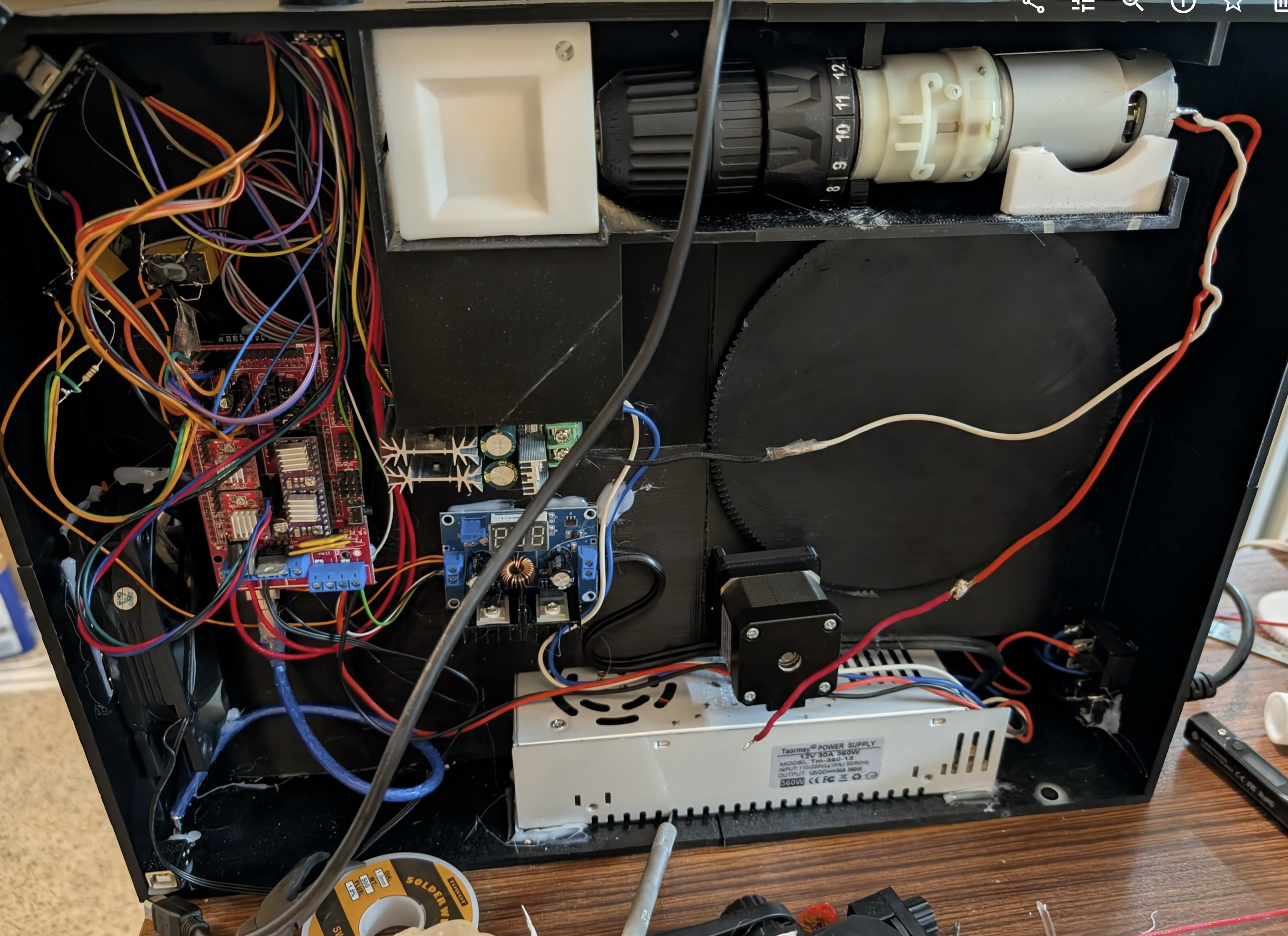
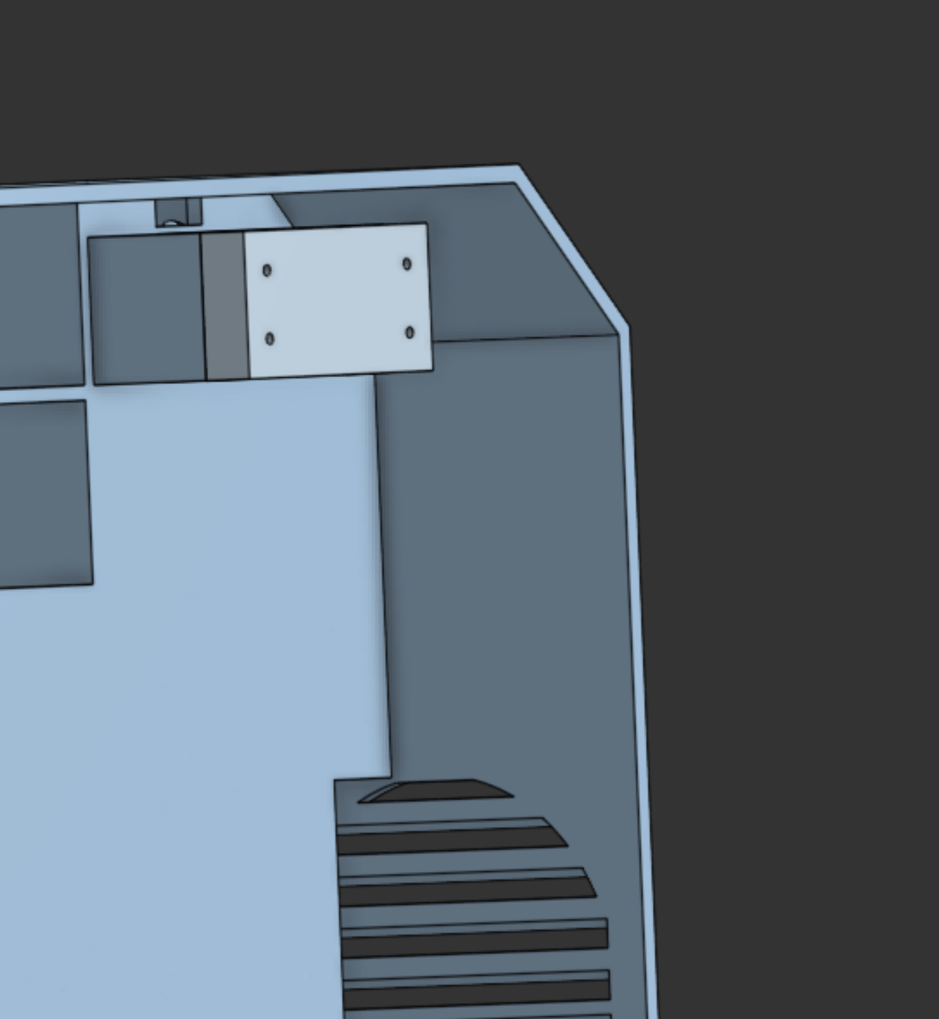
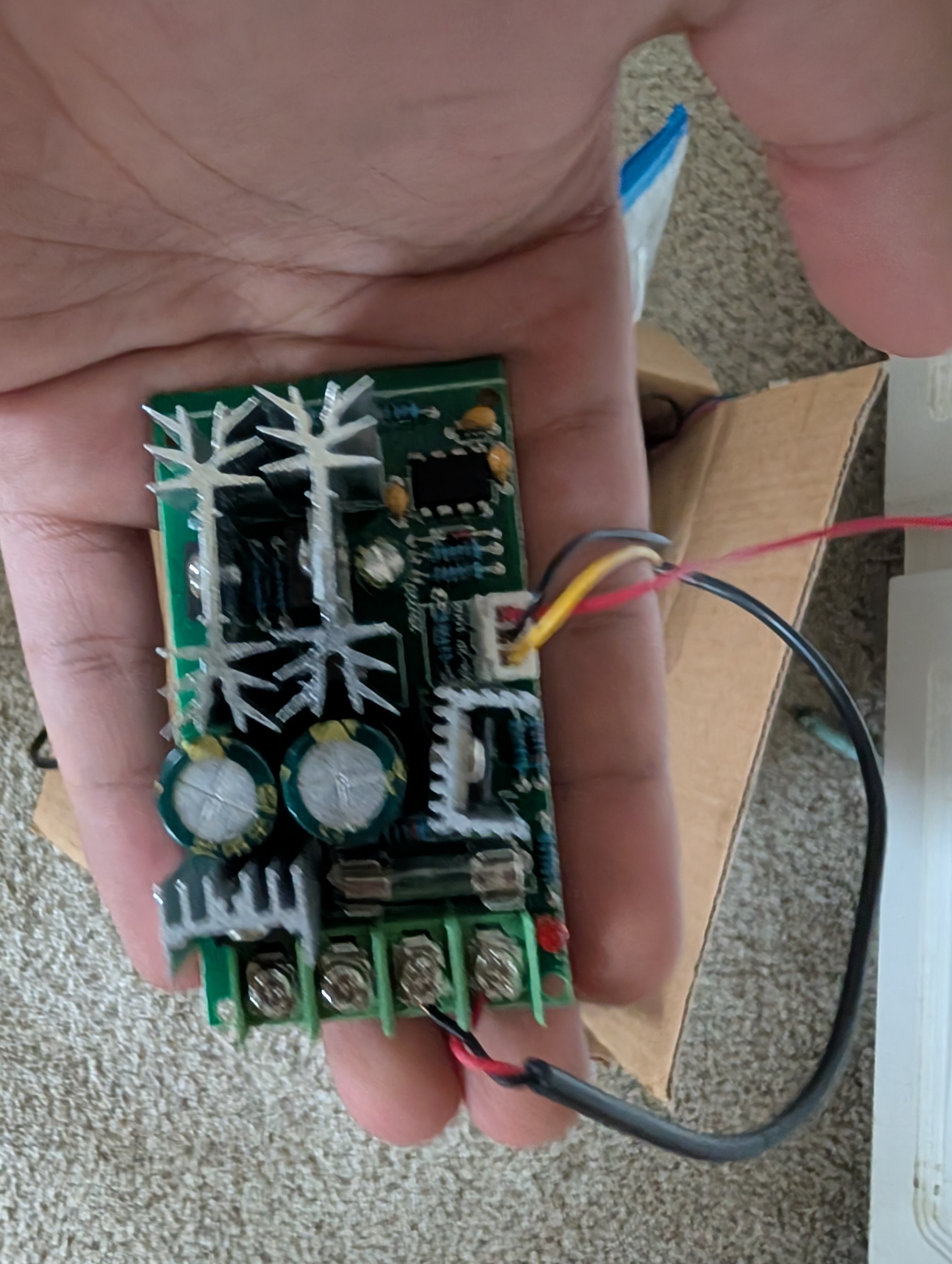
Rear Component Placement fixed!
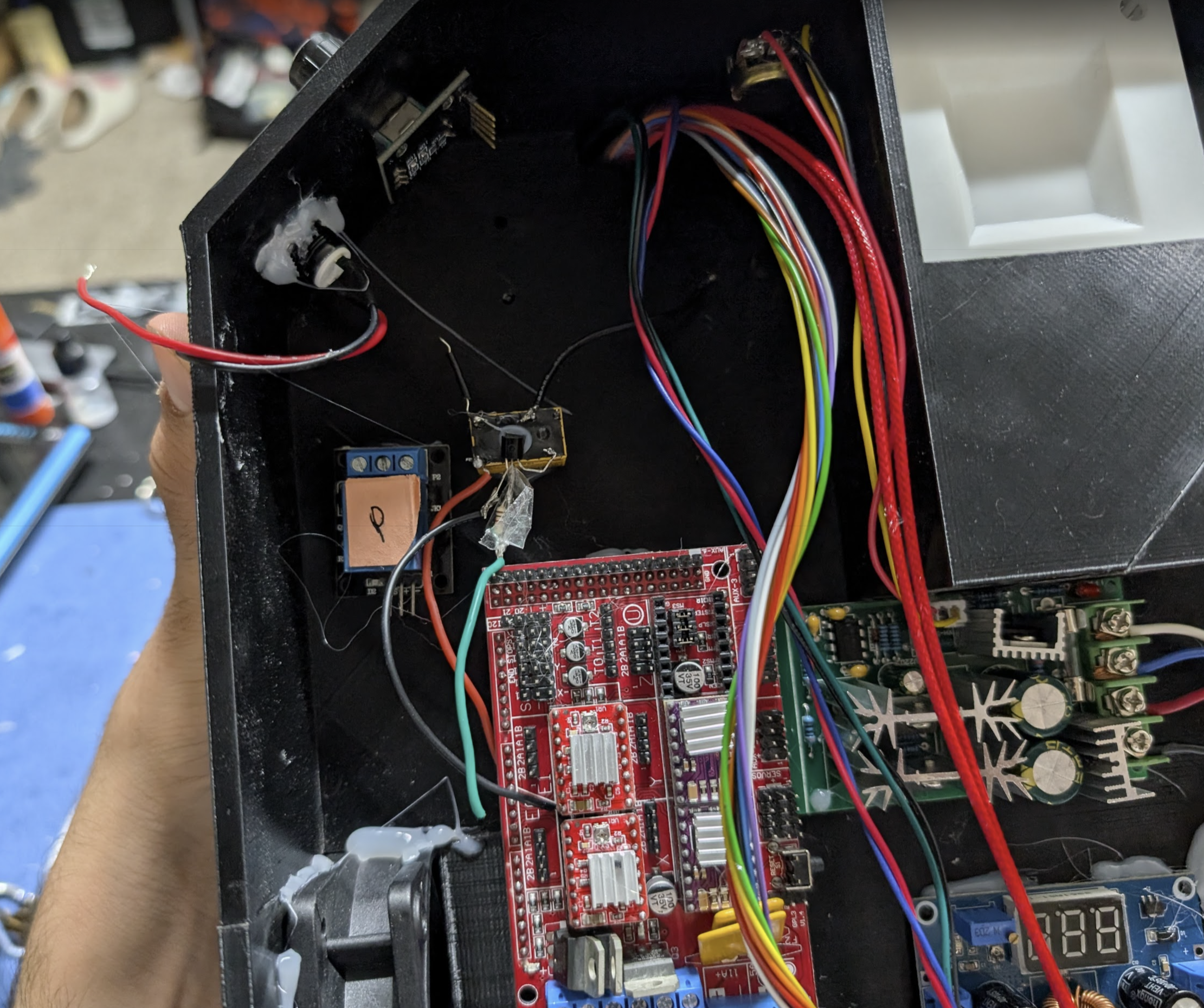
I had glued the ramps 1.4 board and the buck converter to the back before but had messed up and glued them where the stepper motor was supposed to go. So I spent time removing the components, I was scared about this because I did not want to break the PCB but I had to get the parts off. Once I got them off I figured out new placement and triple checked everything before gluing it down. After the hotglue set I got all the power wires routed and connected. While going so I broke the solder on the switch that I had solded 5 times before already so I got some extra flux scrached the surface of the switch prong then going into that akward spot with a soldering iron I got it togeether.
Now all componets have power
Arnav Purbiya
added to the journal ago
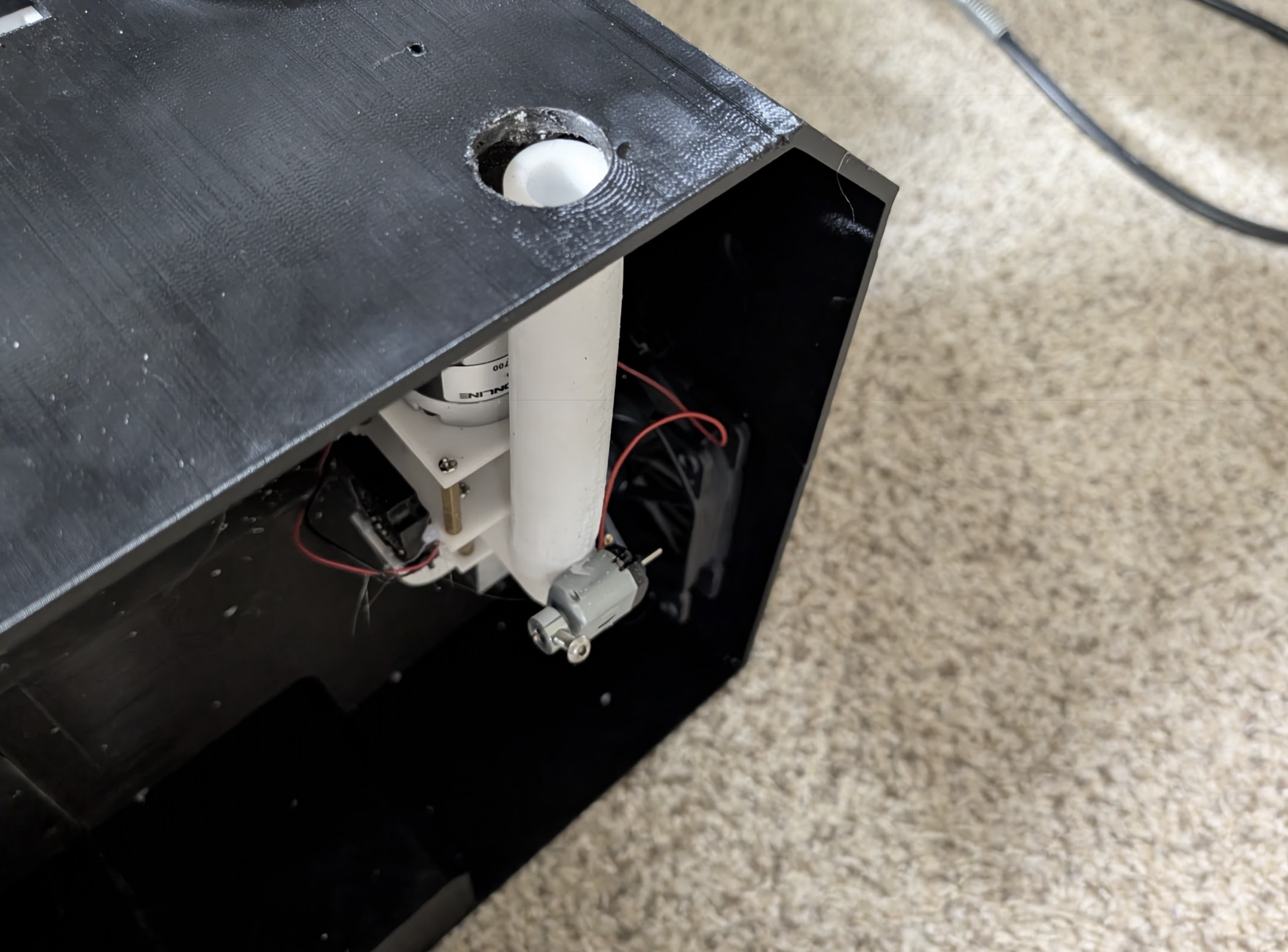
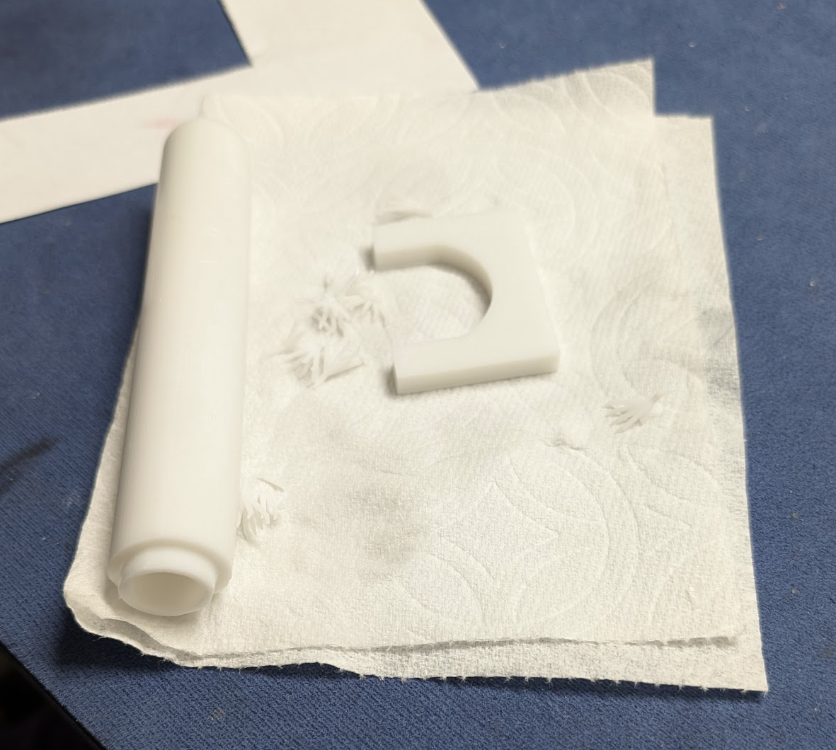
Extruder Assembly V3
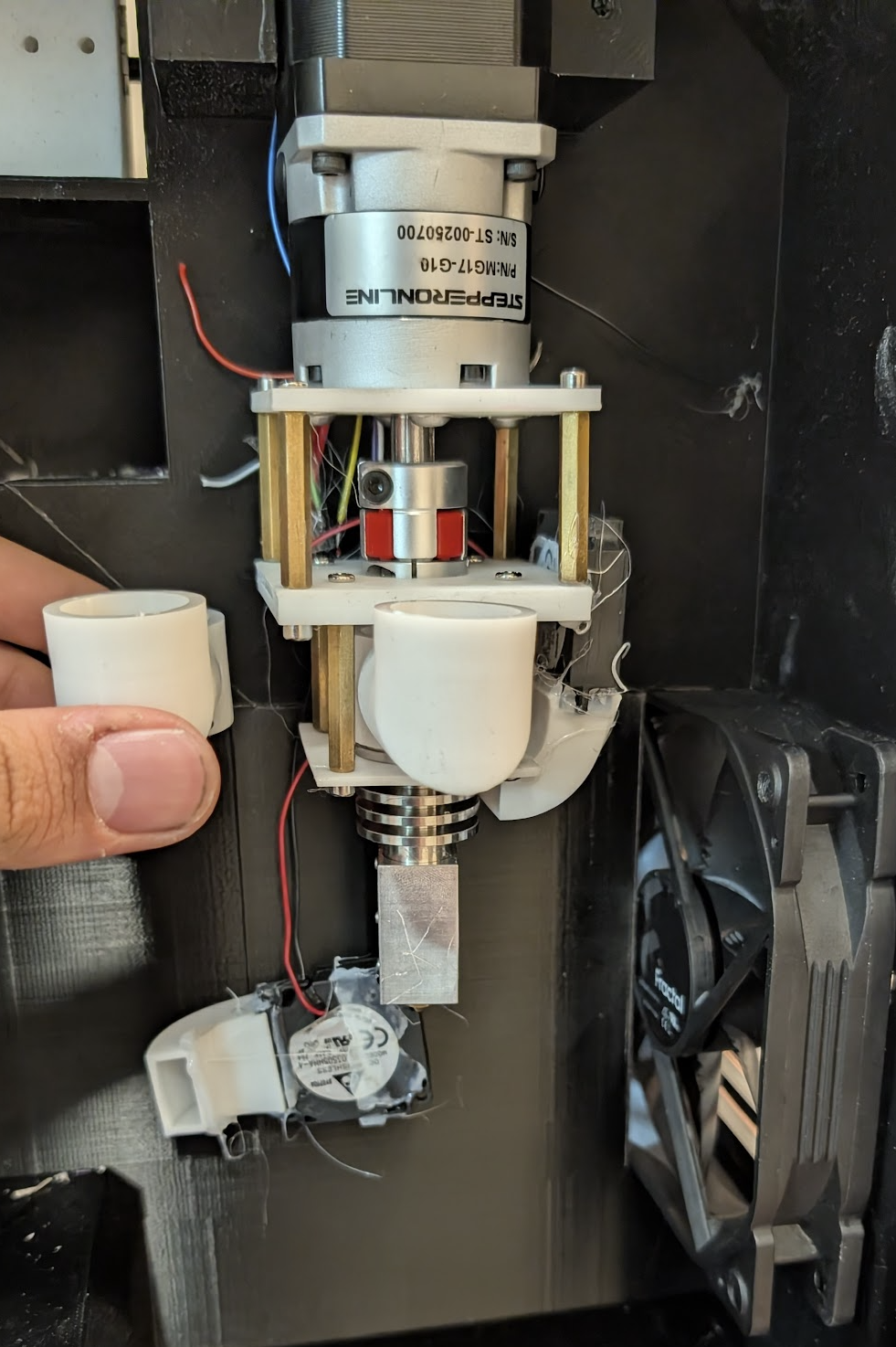
While I was installing the extruder I riped one of the fans off, and I need to replace the chute as well. Luckly I had the new shorter one printed already, so I started by removing the prints and cleaning them off. The chute was easy the shredder part which was on the same build plate was a pain because I had to drain all the resin out from inside by flushing it with some IPA. But after that was all done I cured and the started un screwing the extruder to replace the chute, after than I put most of it back together and got the both the fans hot glued back on. I also added a dc motor with a off set screw to act like a vibrator to help avoid clogs in the chute. I put everything back together. I was trying to get the extention pipe on when I realized the hole in my 3d printed case what not big enough. I hand sanded the hole until it was big enought. That was all I got done. Next I need to fix the electronics on the back
Arnav Purbiya
added to the journal ago
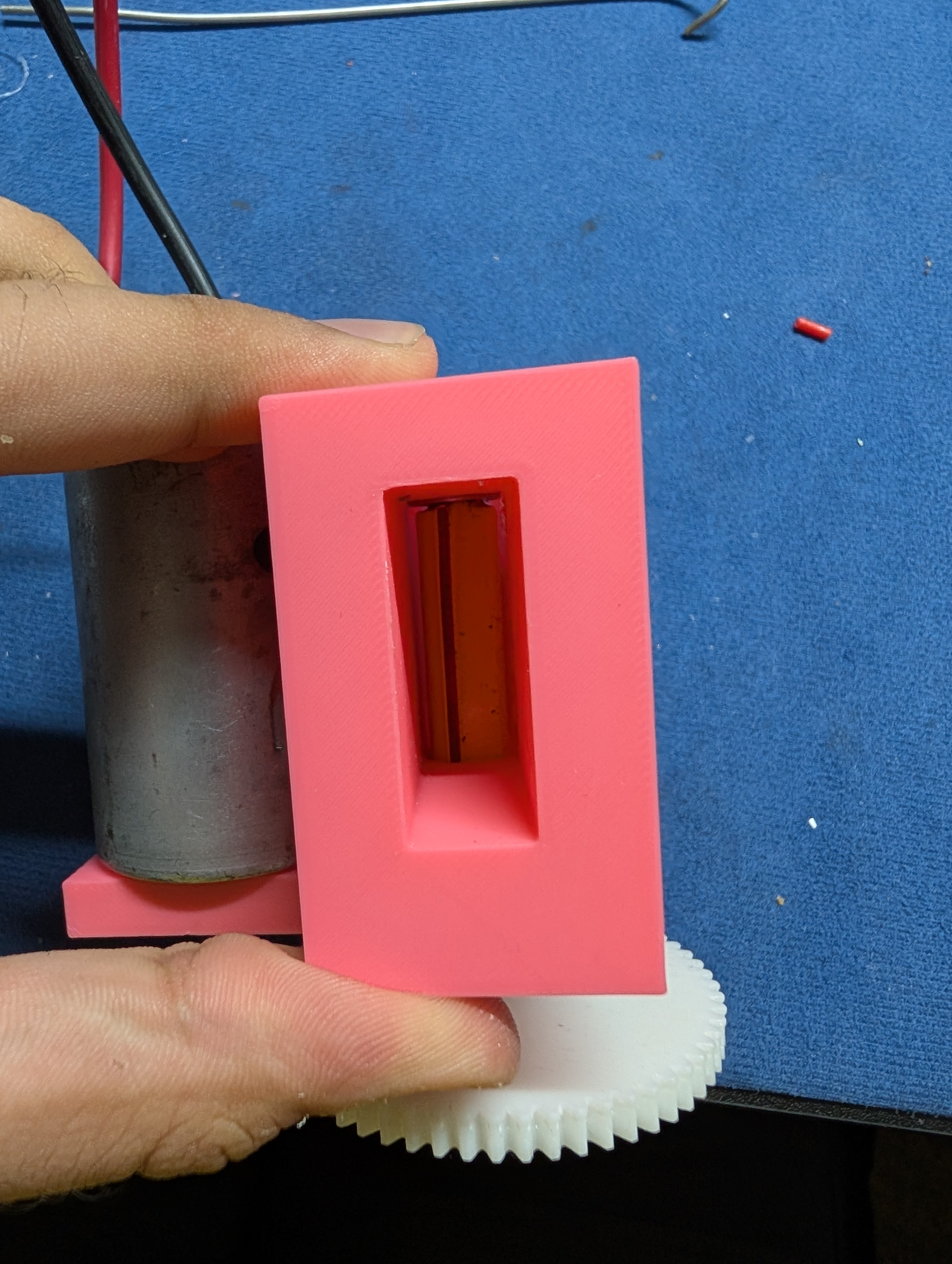
Assembling Components
Since I had the main frame all printed I started getting all the components in there clued up. I started with the psu the plug and the switch. Soldering these wiers were a pain becuase of the angle. the wire fell out like 5-6 times. I wanted to make sure that wire would not fall out cause what was the AC power. Then I started glueing all the compontents and the fan to see how best I could fit everything. I also got the rotory encoder screwed in from the outside for the shredder and the button. I also glued a came for the arduino mega date came extention. After I glued all of that I sliced and stated printing some more parts that I am going to need for the next steps!
Just as I was writing this journal I realized I messed up if you look care fully you will see the arduino mega is glued in exactly where the stepper motor is going to get screwed in. So now I need to figure out a new placement for everything.
Arnav Purbiya
added to the journal ago
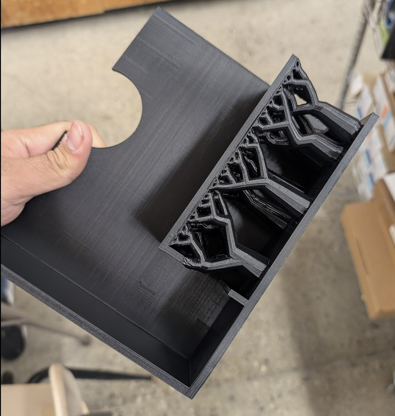
4/4 Prints Done!
The last 2 of the big parts were done printing, I started by getting them off the build plate and then washing both the build plates with soap and water I had put soo much glue that I had to scrape form of the glue off, then I started removing the supports, these 2 had the hardest supports because of the psu slot it was a really large 90 deg overhang. Once I got all the supports off I spent some time sanding all the surfaces that were going to get glued, I went from 320 to 220 on these parts as well. There was a small defect in the first 2 prints so I had to sand extra hard because other wise the parts didn't line up. 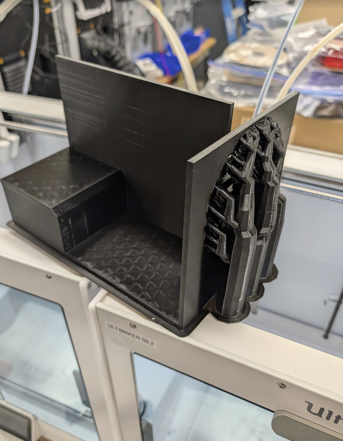
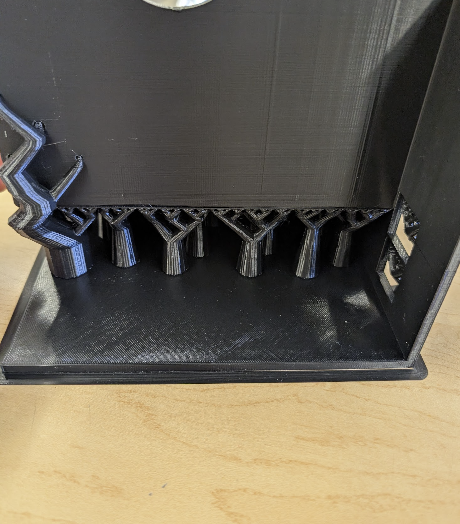
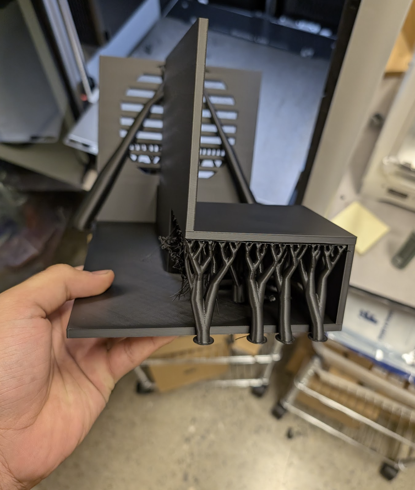
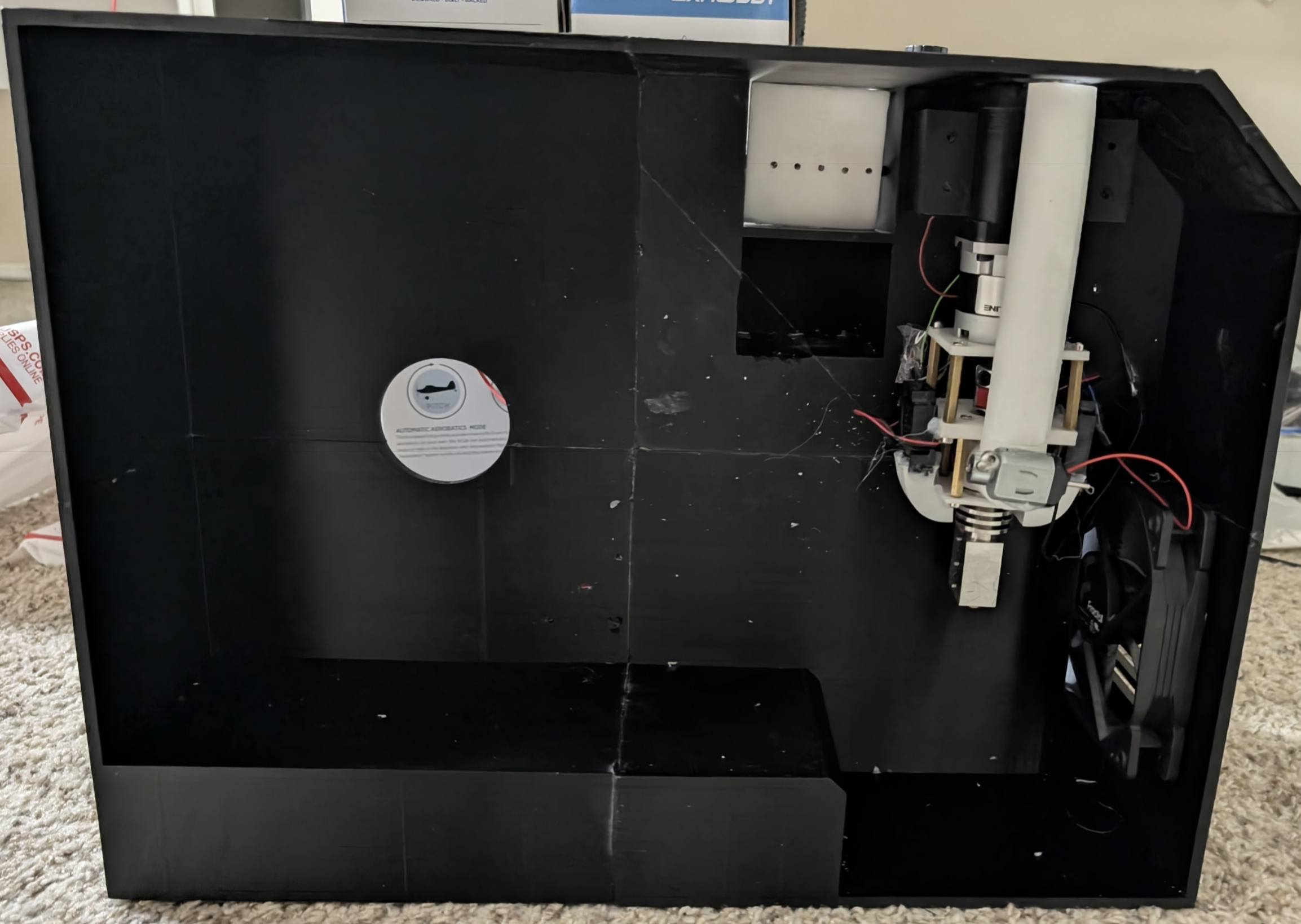
This is the final result, I am ready to start placing all the components in. I still need to print a few components but other than that we are making good progress.
Arnav Purbiya
added to the journal ago
Some more print clean up
I printed 2 more parts that I am going to need in order to put everything together. I printed these in resin so the clean up and post processing to longer. I had already done the cad so all had to do was slices, and then when the print was done some clean up.
Now I have almost all the parts I need to put everything together
Arnav Purbiya
added to the journal ago
2/4 prints done!
I had stated the prints yesterday and today 2 of them were done (kinda) on of the printers tripped the breaker with only 2 hours left but the other print turned out well.
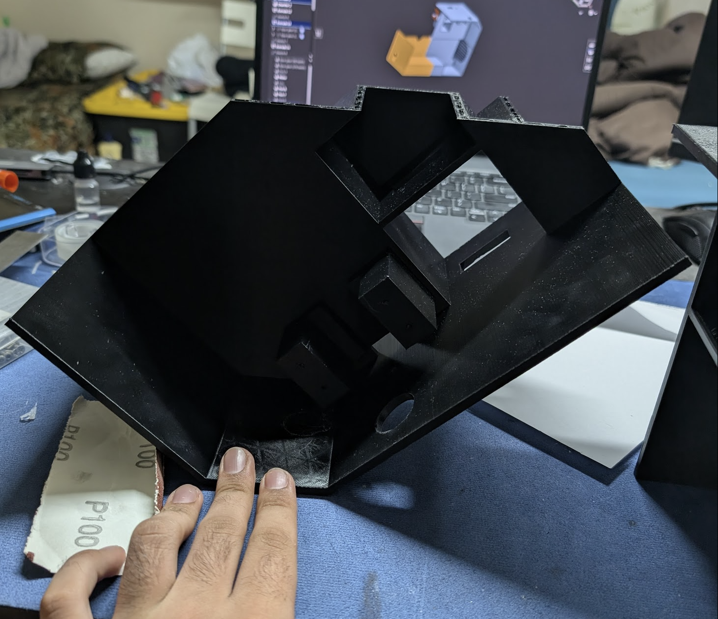
So I measure upto the part that worked re sliced only the falied part and then started that print, once that was done I took it off removed a lot of supports. This was probably the hardest part. At one point I had to pour hot water into the part to melt the supports out. Once I got all of that done I sanded all the edges that needed to be glued first with 320 grit to flatten and then with 220 to score it a little for the glue to work. Then I used medium CA glue to stick the 3 parts toether.
I also got the other 2 prints started so I should have them by tomorrow.
Arnav Purbiya
added to the journal ago
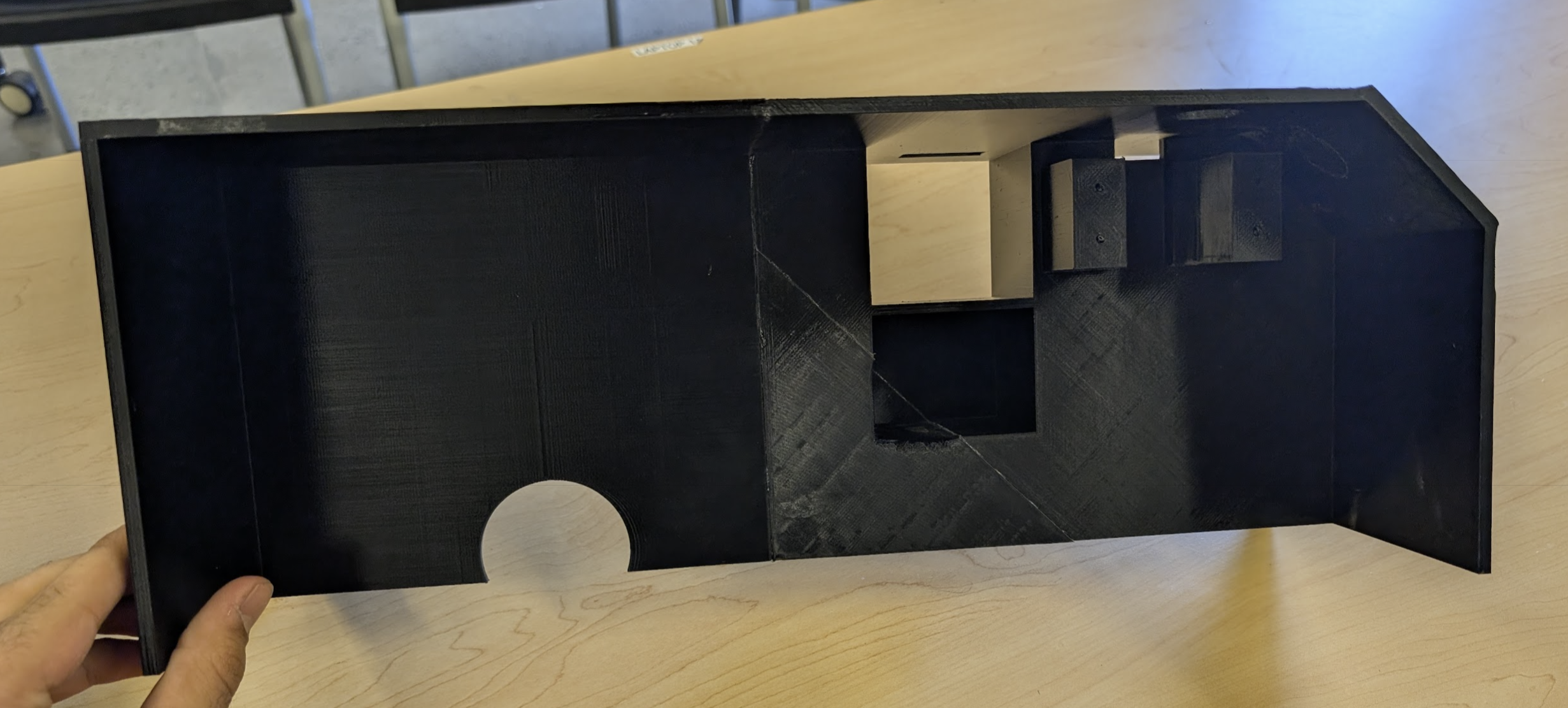
Slpit, SLiced, and Printing
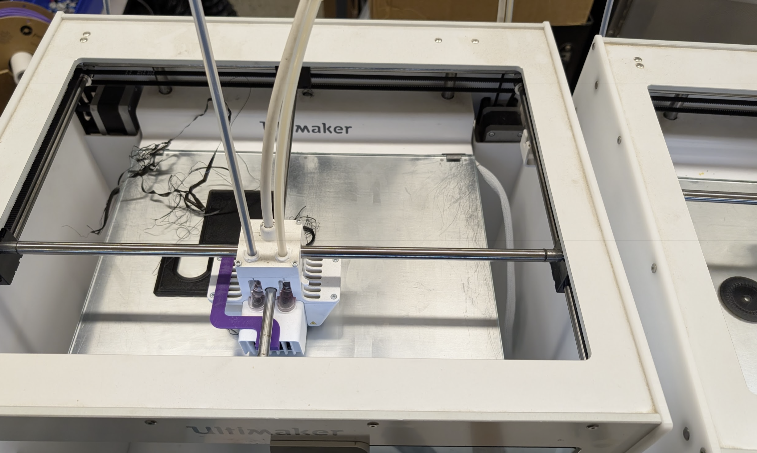
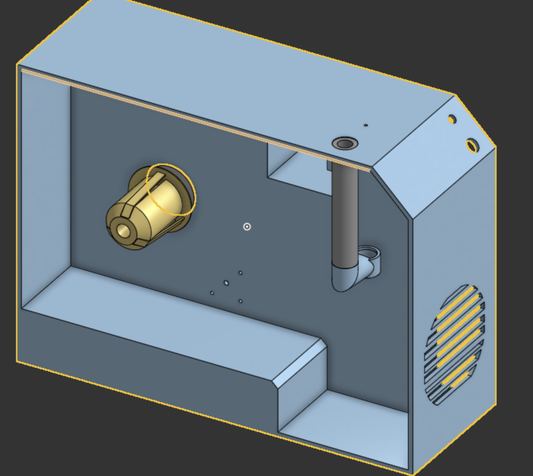
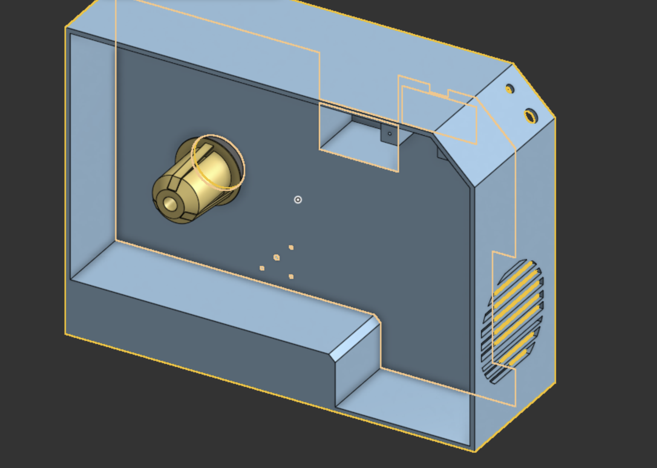
I stated by cutting the main body cad into parts that could be fit on the build plate of the printers at my school. I also had to see what way to split would affect the least amount of featurs. This is how I split it up
Then I opened up cura and then one by one sliced up all the parts, this is when I reallized in there default orientation it would take lot of supports and 30h per part, so I started messing with orientation. Once I was happy with all of this the saved all of the files. At this point each print would take 24 hour :(
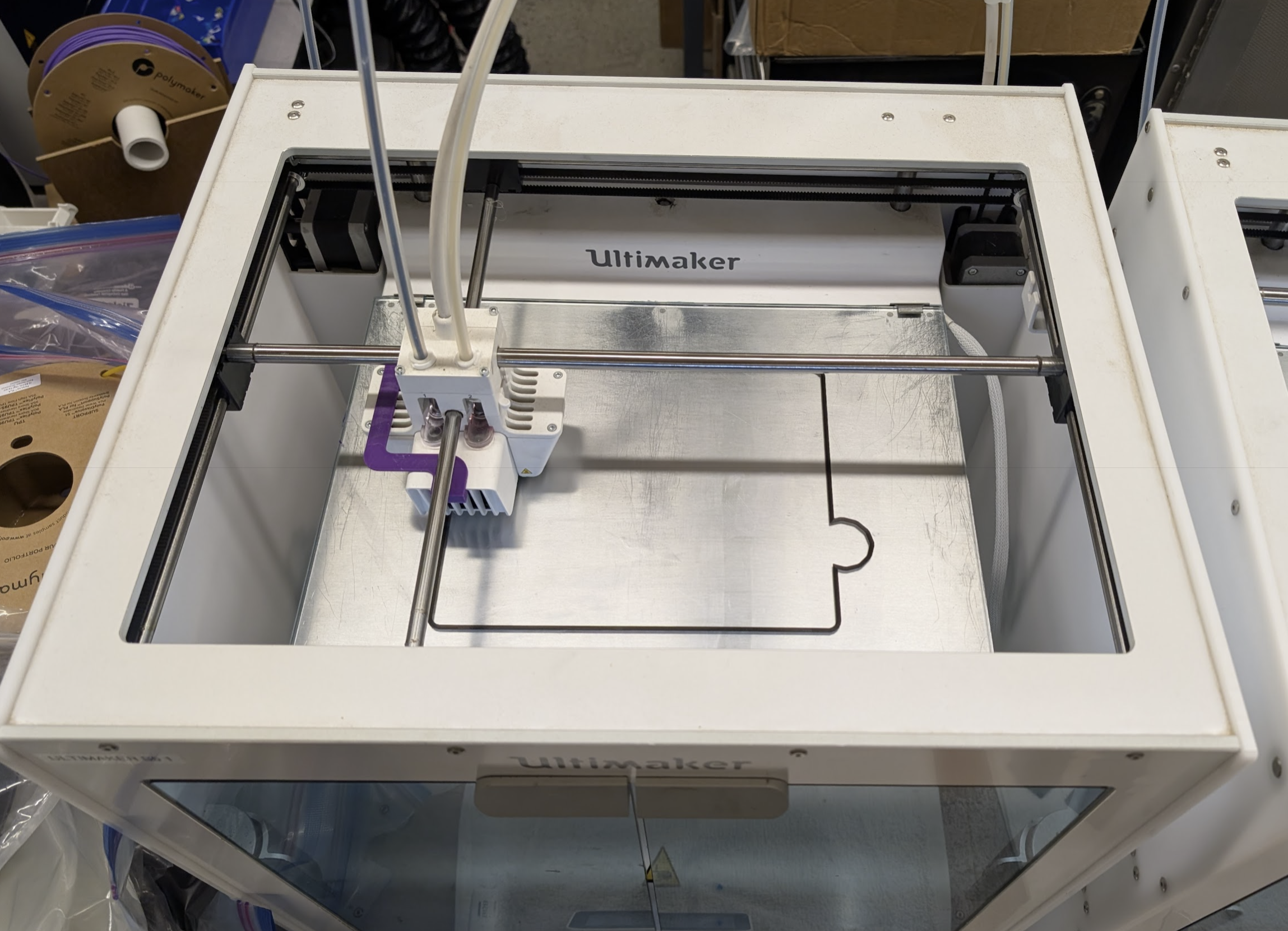
Then at school I got the printers set up by trying spools thta had been dryed over night and calibrating the print cores of the ultimaker s5 (there were 2 printers)
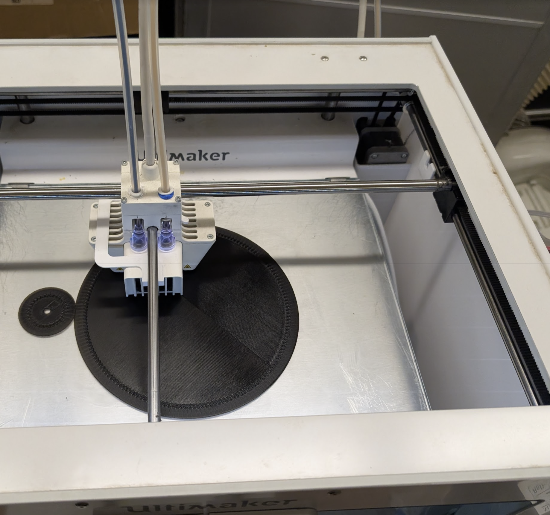
Then I started the print and checked to make sure the first layer was coming down okay.
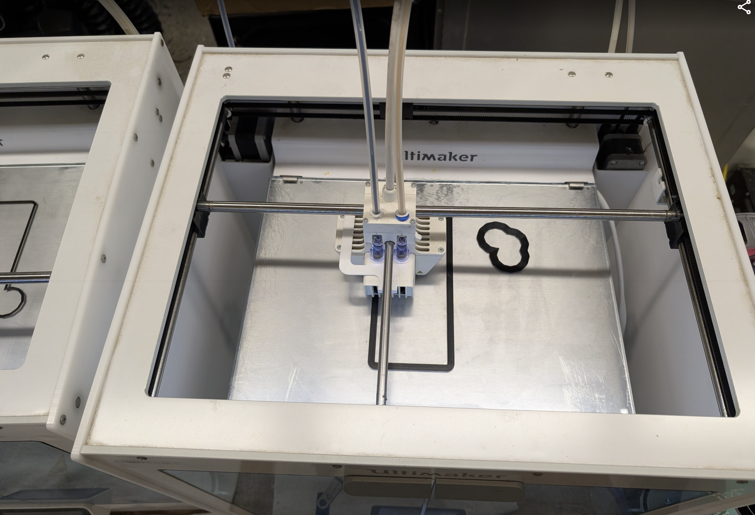
When I went back to check after an hour I realized the nozzel got clogged cause this is what I saw
So I used the neddel first then did a few cold pulls to solve this and then started the print again.
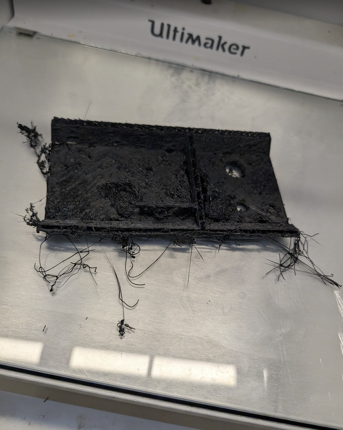
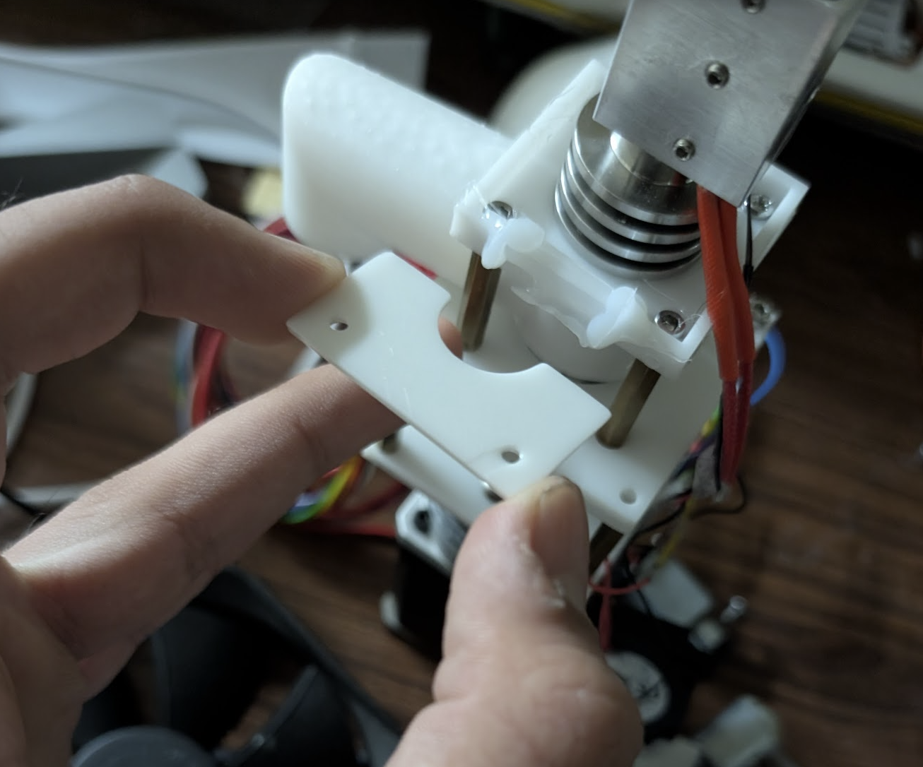
6 hours into the print I realized something about that cad
This part the holds the motor in place should have been a seperate part and I should screw it in so I can adjust where it needs to be.
So the new plan is to let the print finish and then I will just cut the current part out if it doesn't work and print just the part and then screw it in.
Arnav Purbiya
added to the journal ago
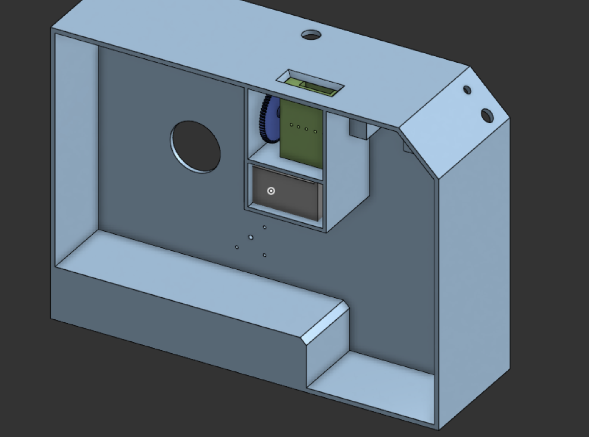
Shredder Assembly Test and CAD
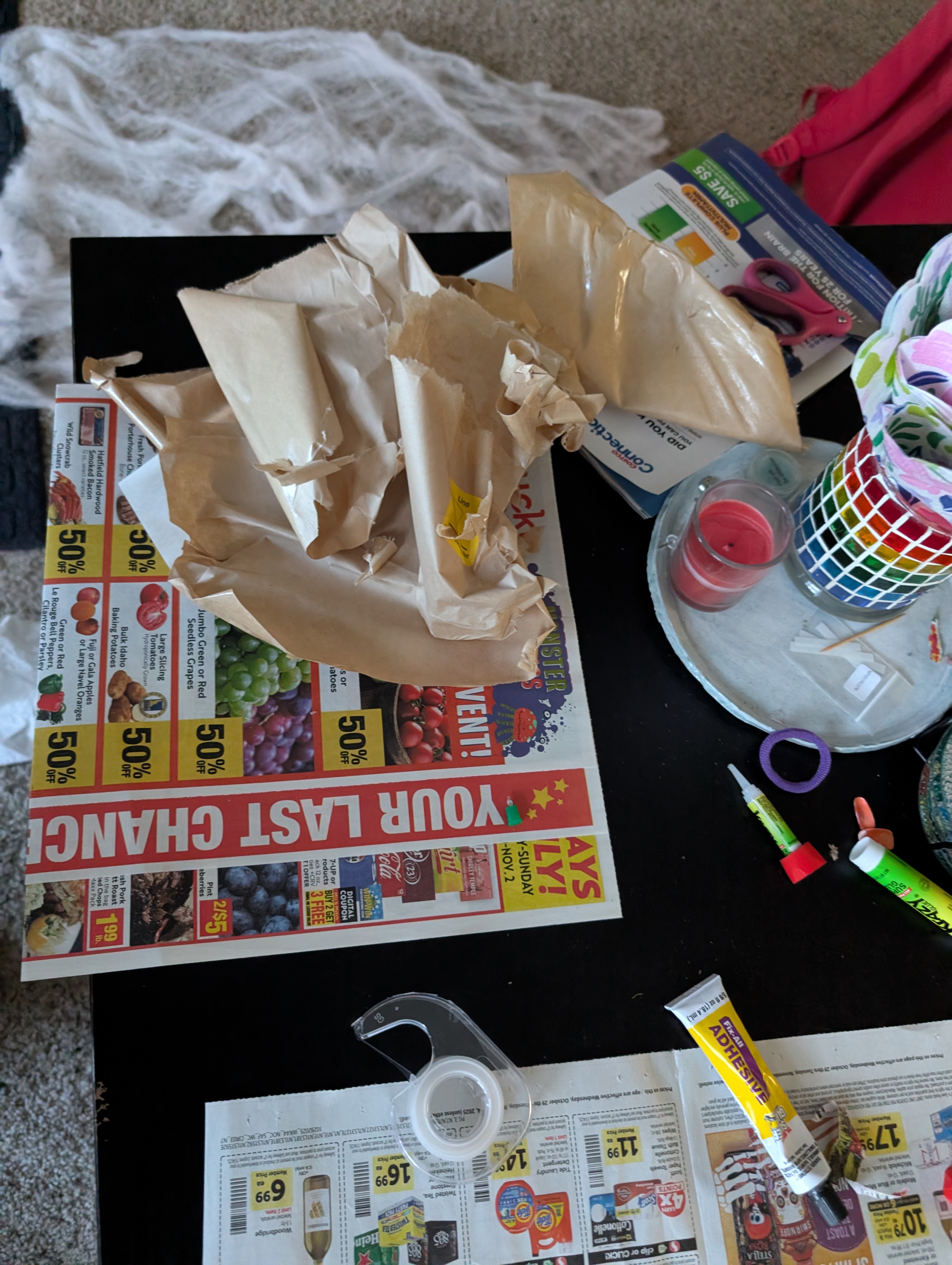
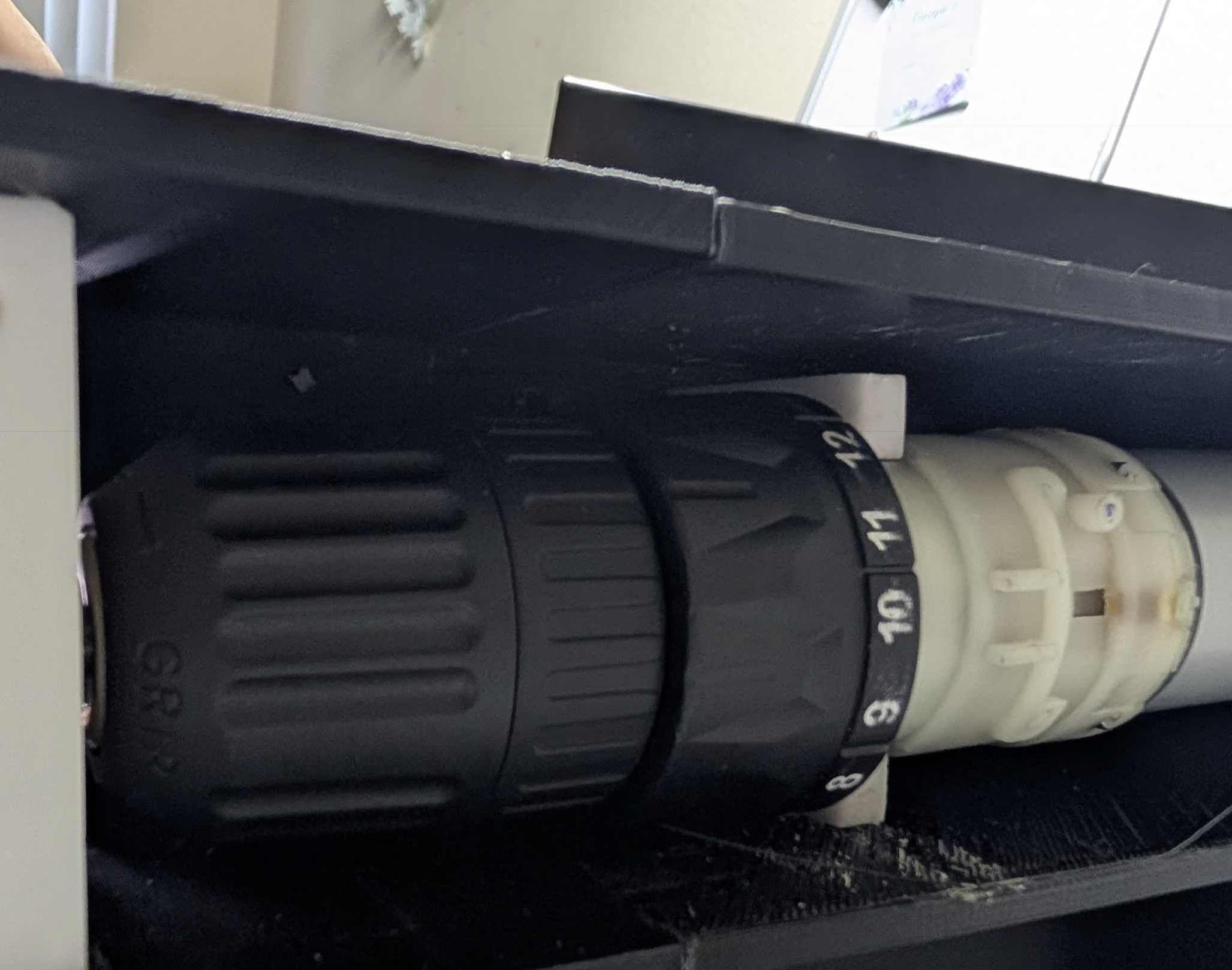
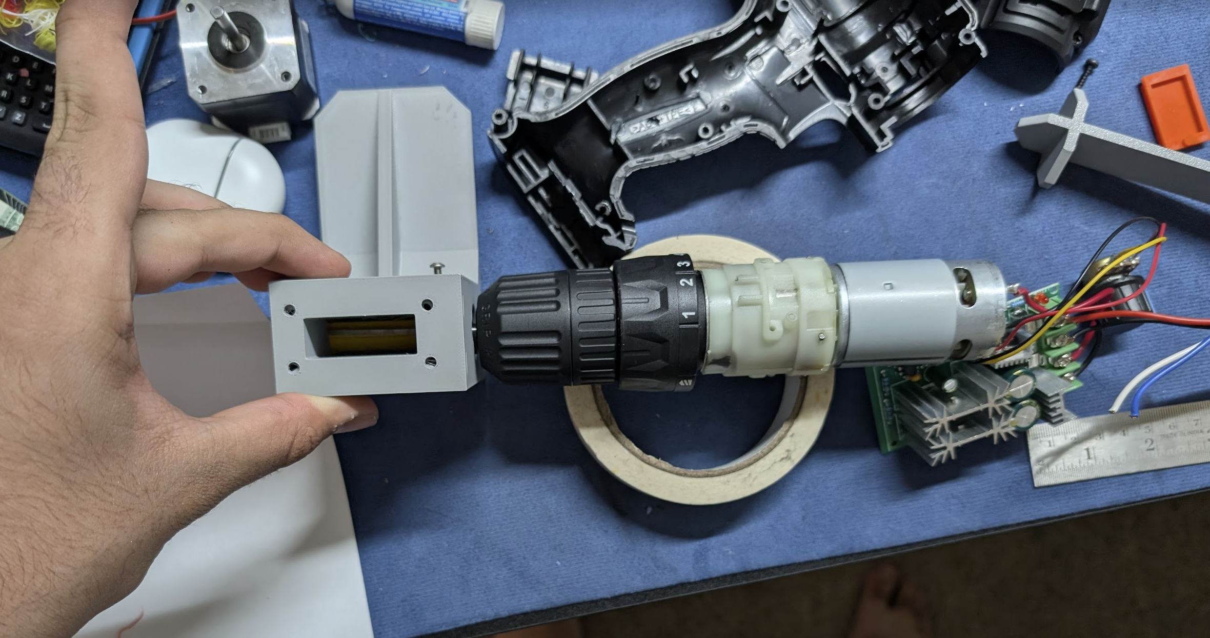
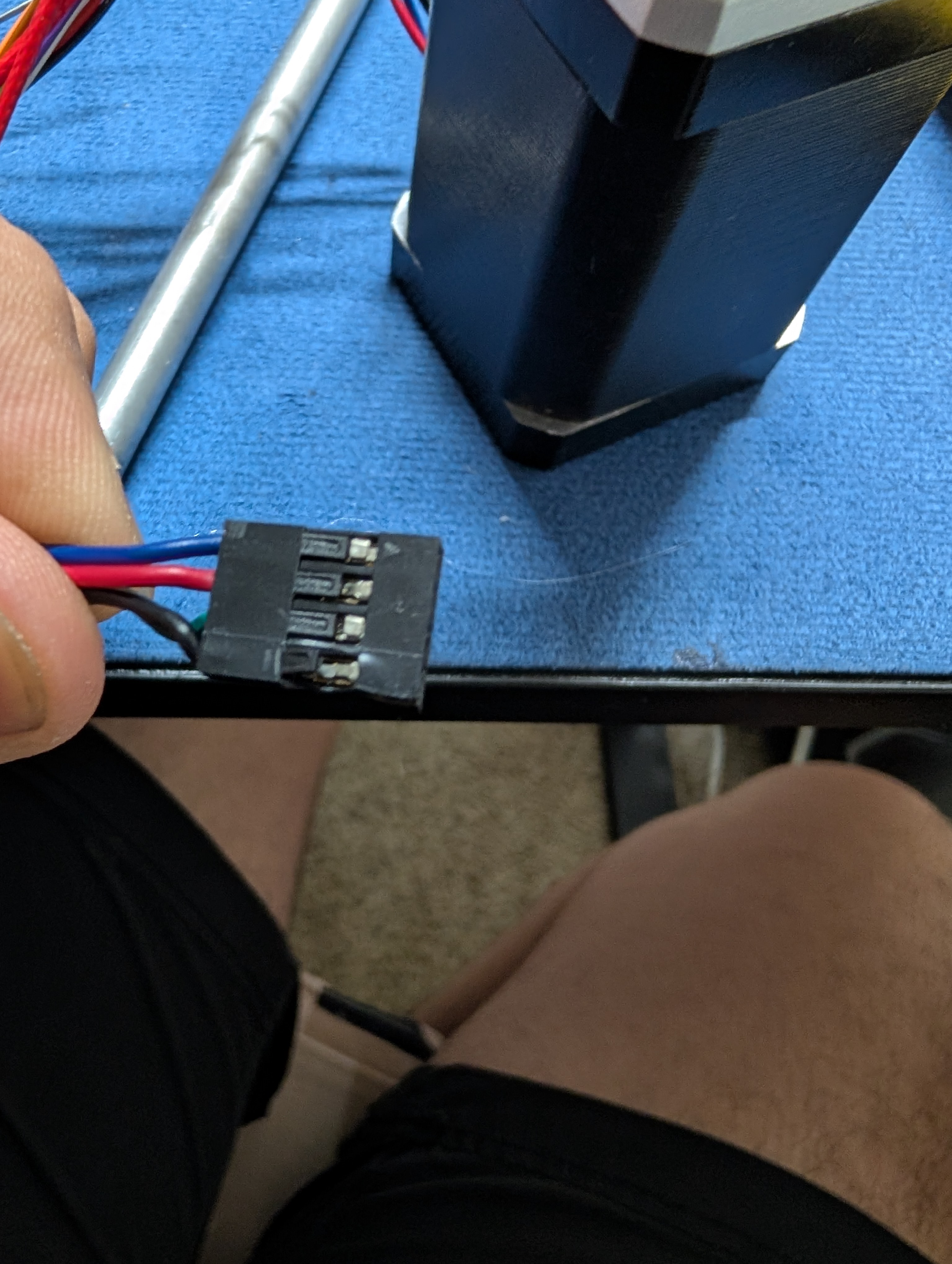
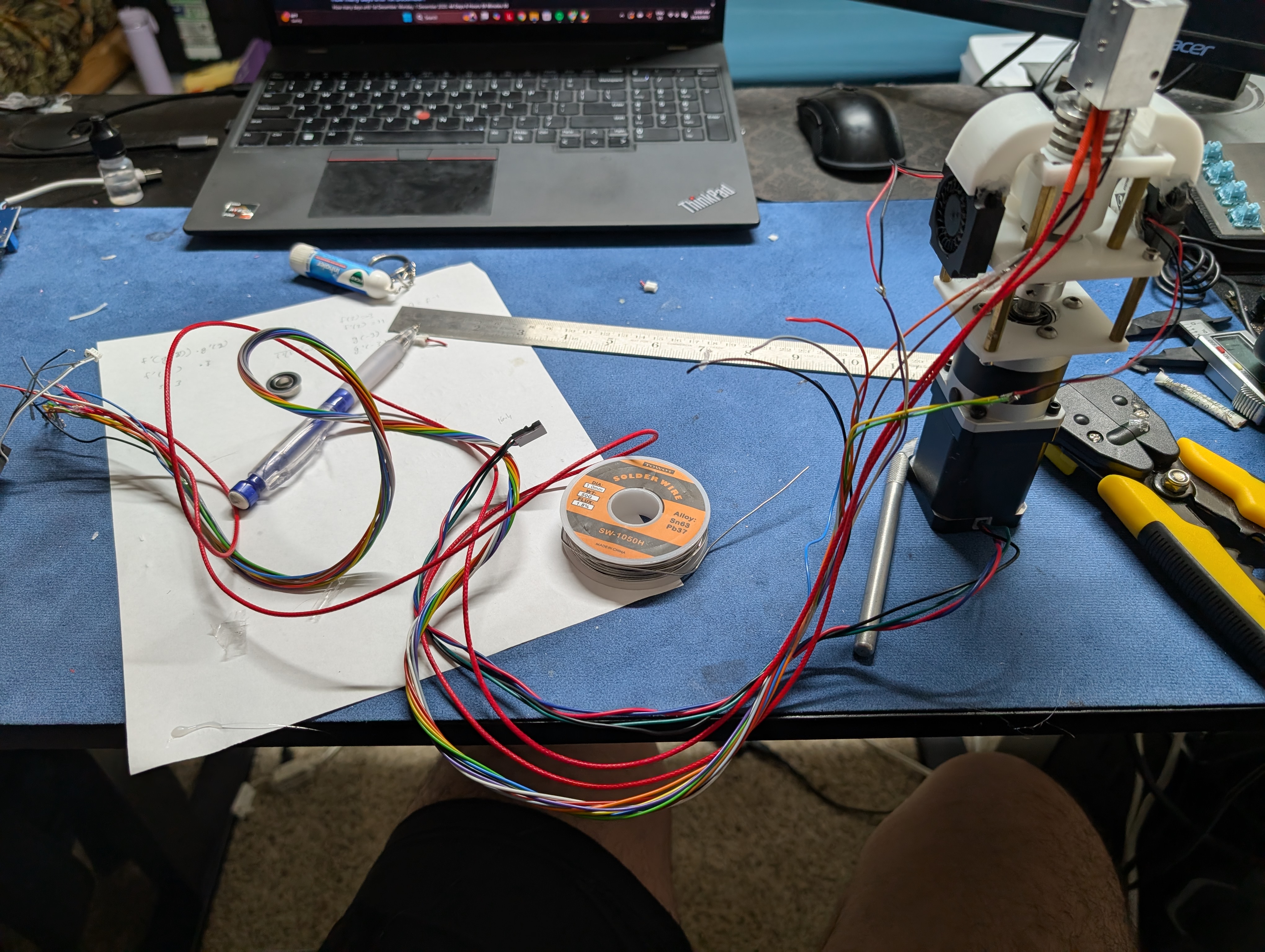
The drill arrived, so I started by taking it all apart for its motor and gearbox system, this is causr my original idea with that 775 and the 5:1 gear ratio did not work. Once I took the drill appart I and to de-solder the motor because I did not want to use that control cuircetry.
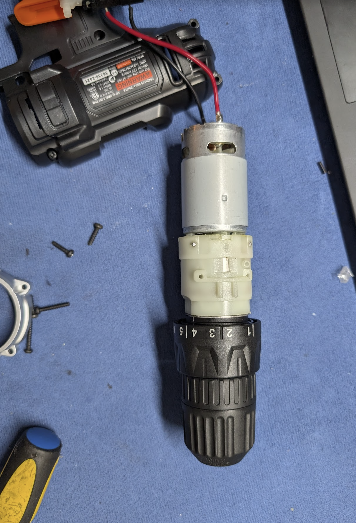
After that I attached my router bit to the drill and connected the wiers from a 12v psu and the motor controler. After which I started slowly testing if this could shred stuff which it could. While testing this is what my table looked like
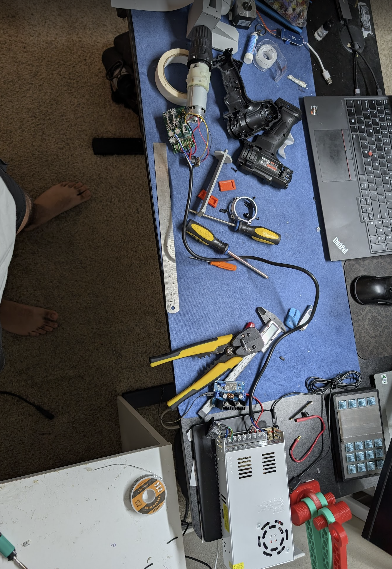
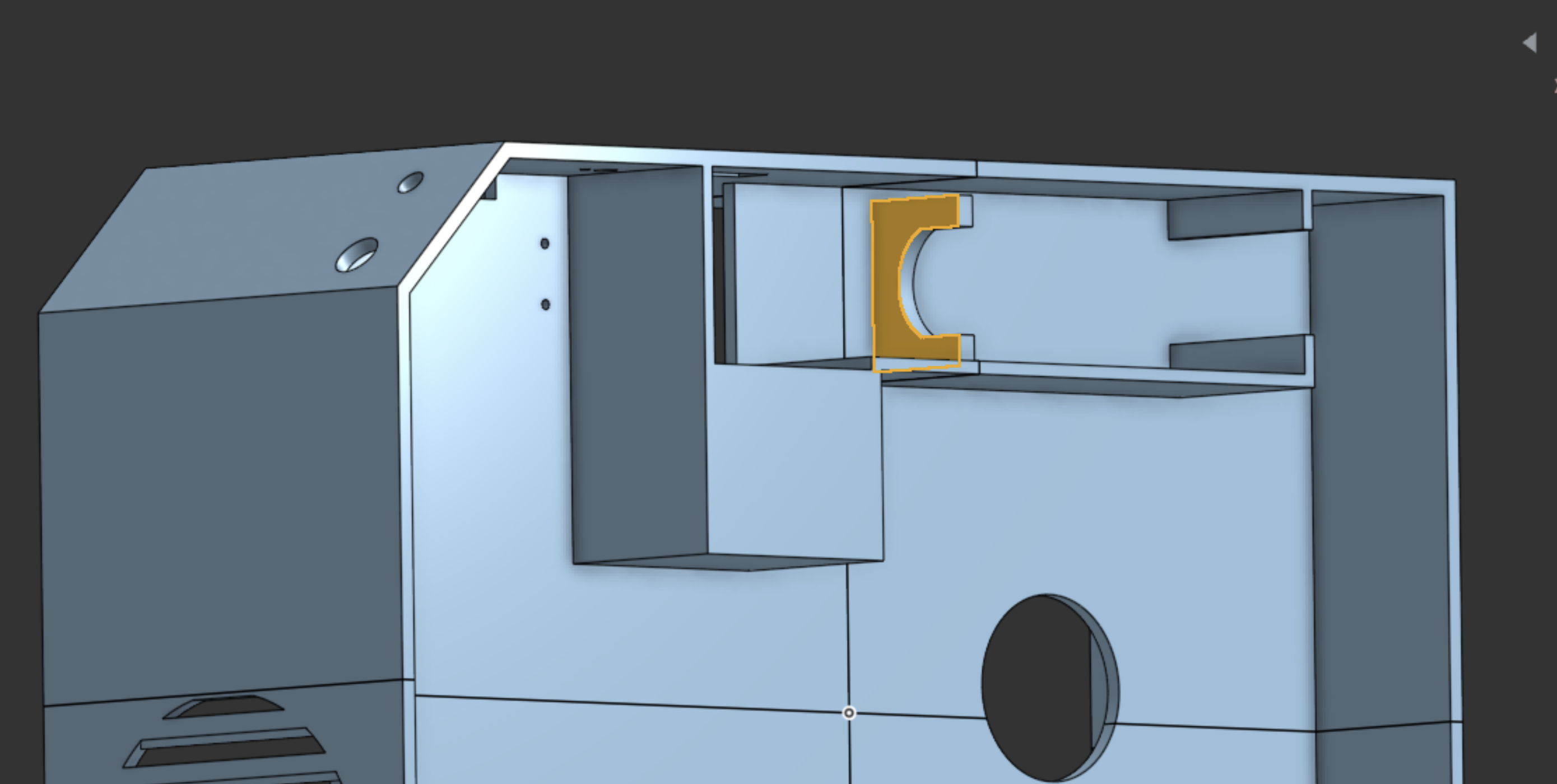
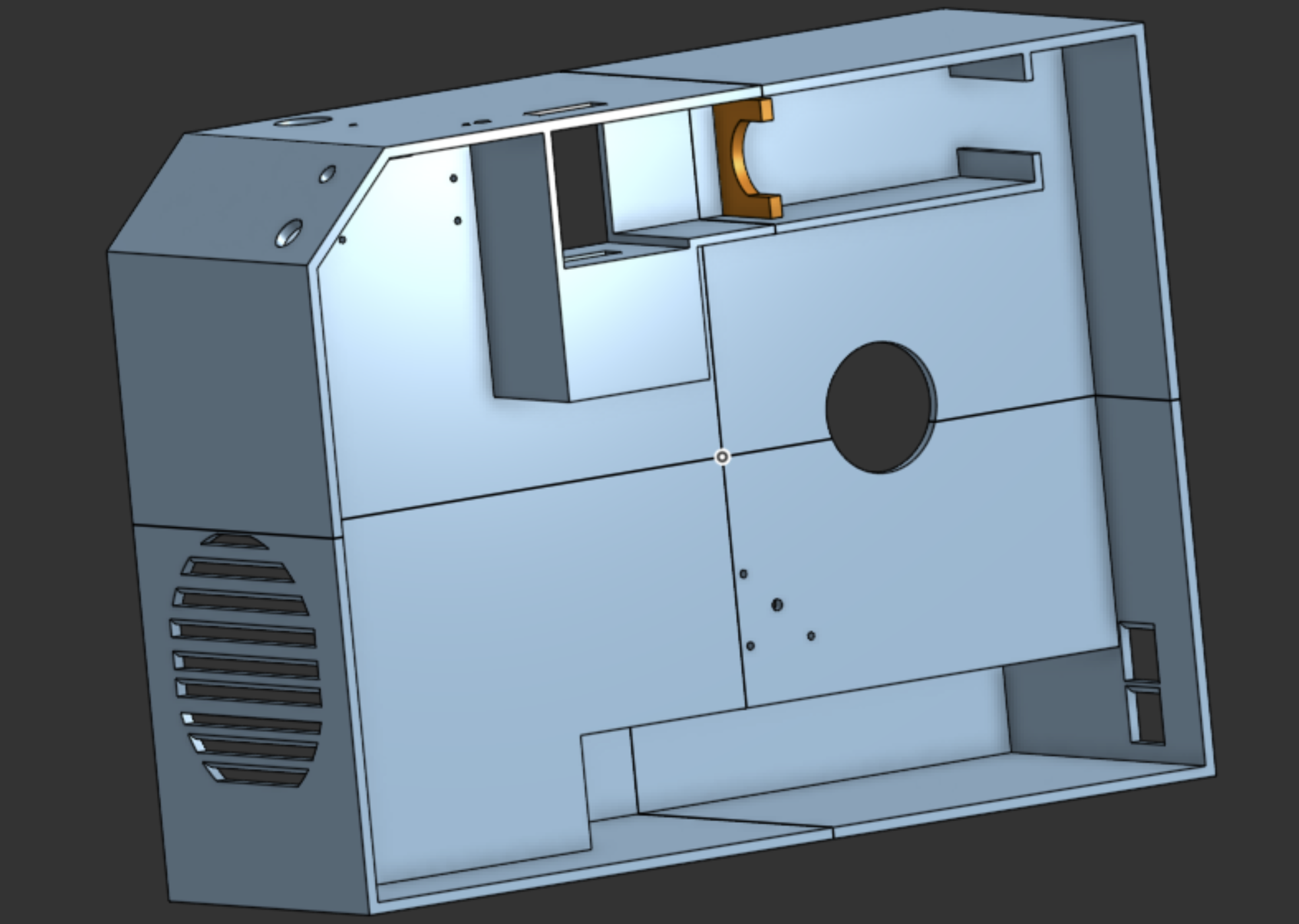
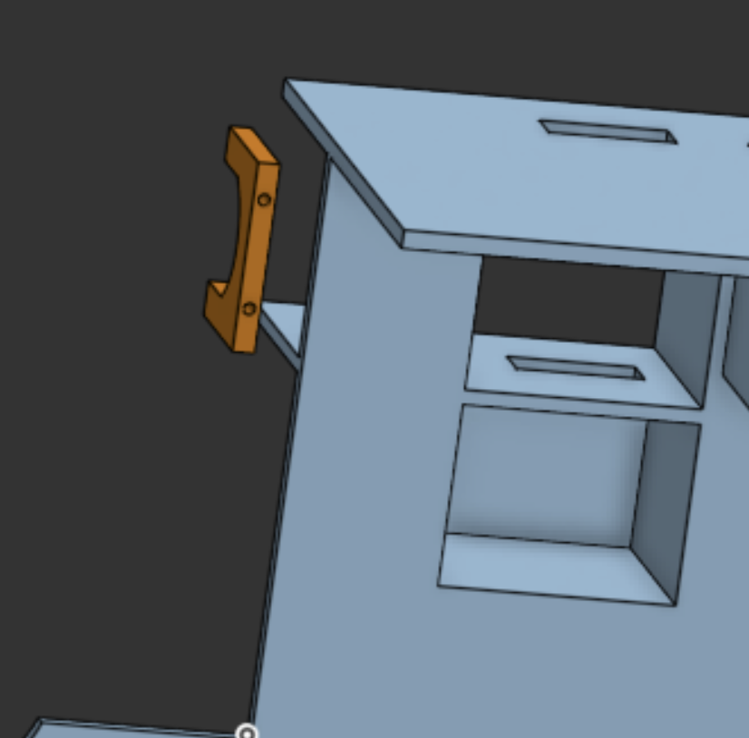
Since this set up was able to do its job, I moved on to the longer part of fixing all the CAD to get everything ready for printing. I made a slot in the back for the motor and gearbox, made the slot in the top for the shredder and cleaned up all the dimentions
The hardest part in all of this was holding the drill down while testing, becuase the motor body would just spining if I didn't hold it down right thats why the slot in the back is cut out spcificaly to hold the motor
Arnav Purbiya
added to the journal ago
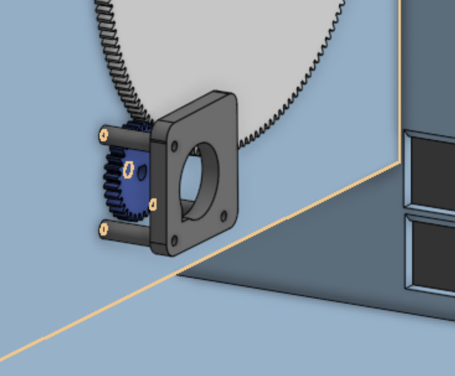
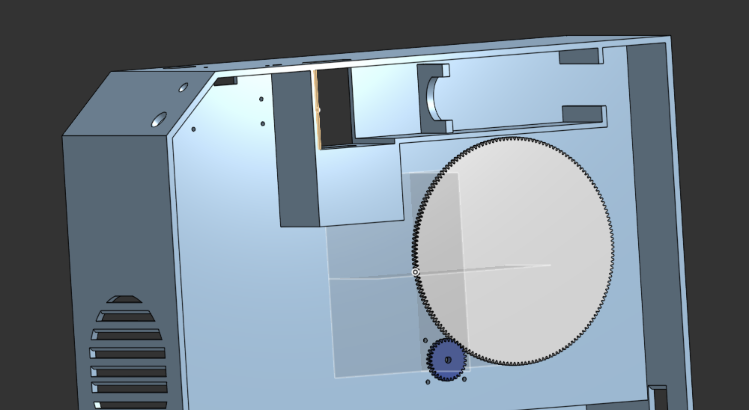
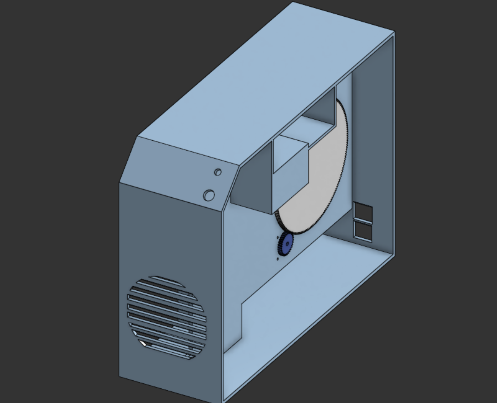
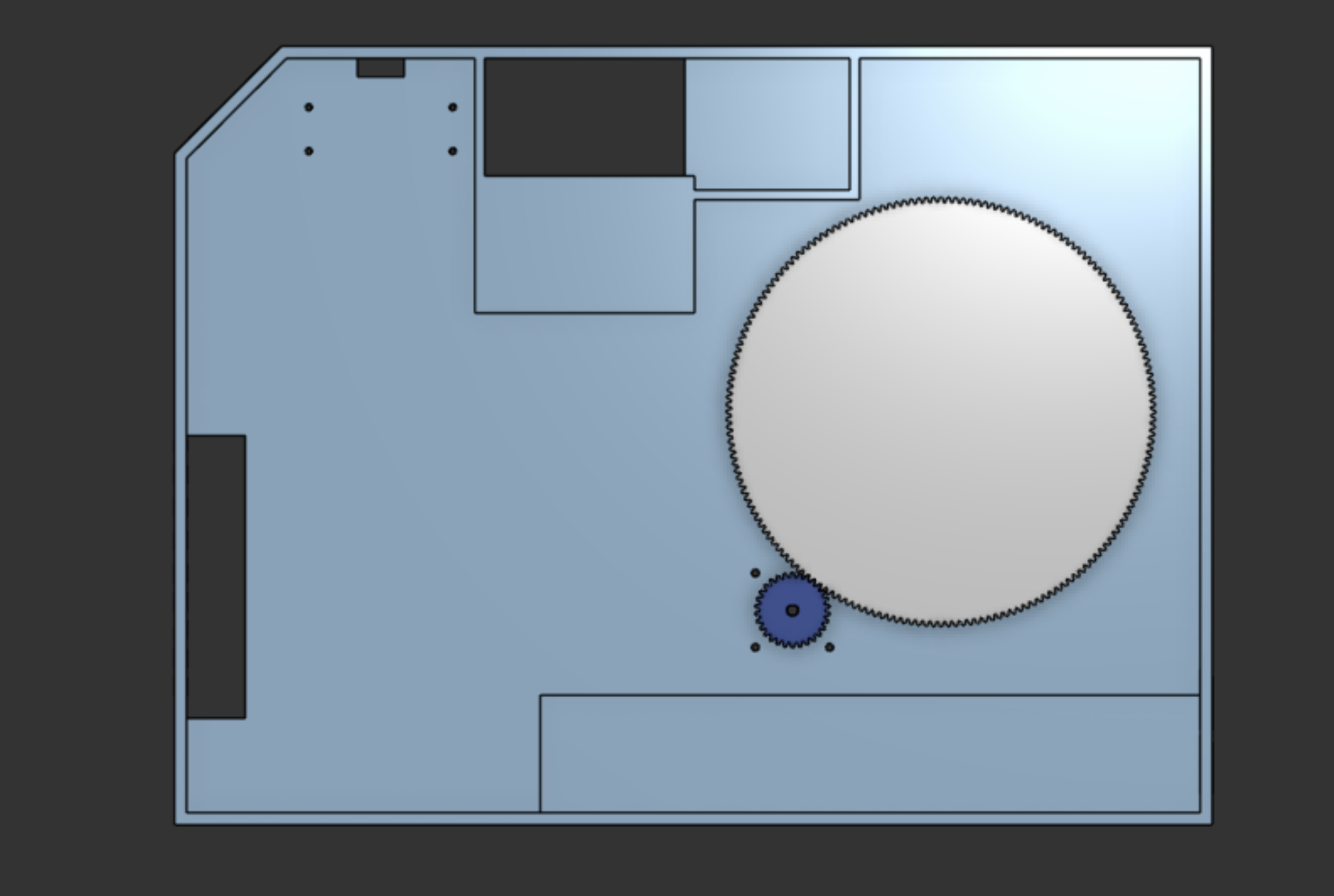
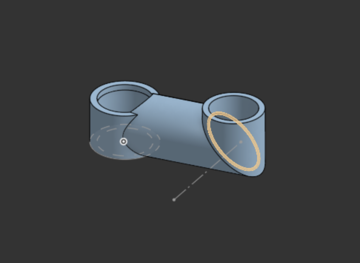
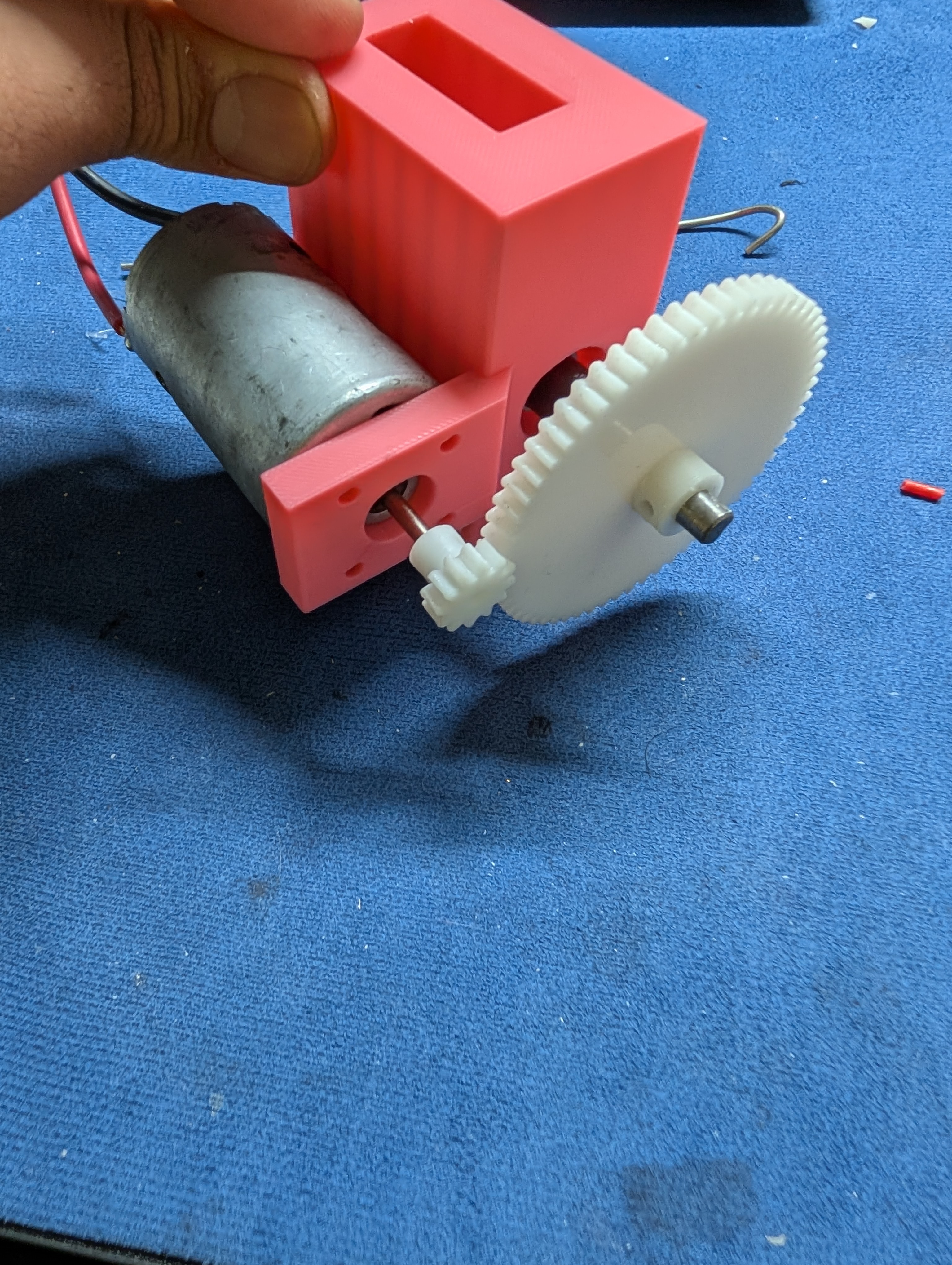
Spooler CAD
I have been worrying less about the spooler untilll now... I finalized the gear ratio I will be using for the spooler to work with a stepper motor the ratio I am planing on using is 170:30. The really big gear needs to attach to a part that can allow a spool to be slotted in which I designed previously. I was planing on printing a rod on the gear and the sliding it on but the rod would be week due to direction of layer lines so I re-did that to have a sort of slot and I am going to glue it in place now.
This is what the gear looks like
and then the AMS lite coupler
I had to firsly do a lot of research to figure out how large the gear ratio needs to be in order for me to get enough power. But once I got that the rest seemed okay. I have to now add this to the list of things I need to print. Before the 170teeth gear I had done 180 based on rough math but I realized that was too big almost 18cm across.
Arnav Purbiya
added to the journal ago
Some CAD and assembly
Got a lott of work done today, started the day with printing and cleaning up a print to replace one of the extruder plates that was cracking, the print was 6 mins but then cleaning curing took a while.
then in the afternoon I worked on cad I did some of the math to figure out where the pellet pipe would go and then designed the pipe and added that all to the assembly
I also had to clean up some of the files, and then I organized the git hub repo so all the cad files are in order.
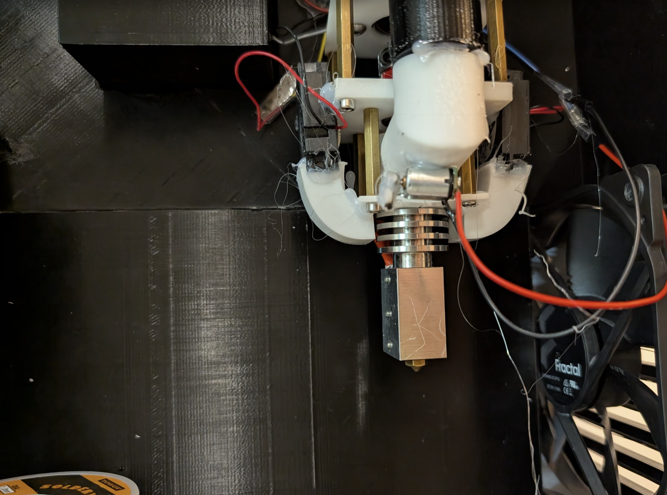
Then I assembeled the plates that I printed in the morning onto the extruder, I also had to glue the 2 fans back on. I used like 10x the hot glue I used the first time to make sure it stays stuck this time.
I am very close to start printing all the parts, the drill arrives tomorrow. I am going to take it apart for the motor then I will make the changes in the CAD for the drill and then slice to start the prints.
this is what the final extruder looks as of right now
Arnav Purbiya
added to the journal ago
More CAAAAD
I know I said I am not doing CAD anymore but I wanted to get some more work done. Here is what I got done. Created the gears for the spooler system, also made the mount which kinda works like the AMS lite mount. Made the fan vent and then resized the shredder part to maybe fit and drill and the shredder, I also made the holes for the stepper motor mount of the extruder and the cover plate for that.
All cad is on onshape for now, I will put it on Git Hub when I get some more work done and it looks better.
Arnav Purbiya
added to the journal ago
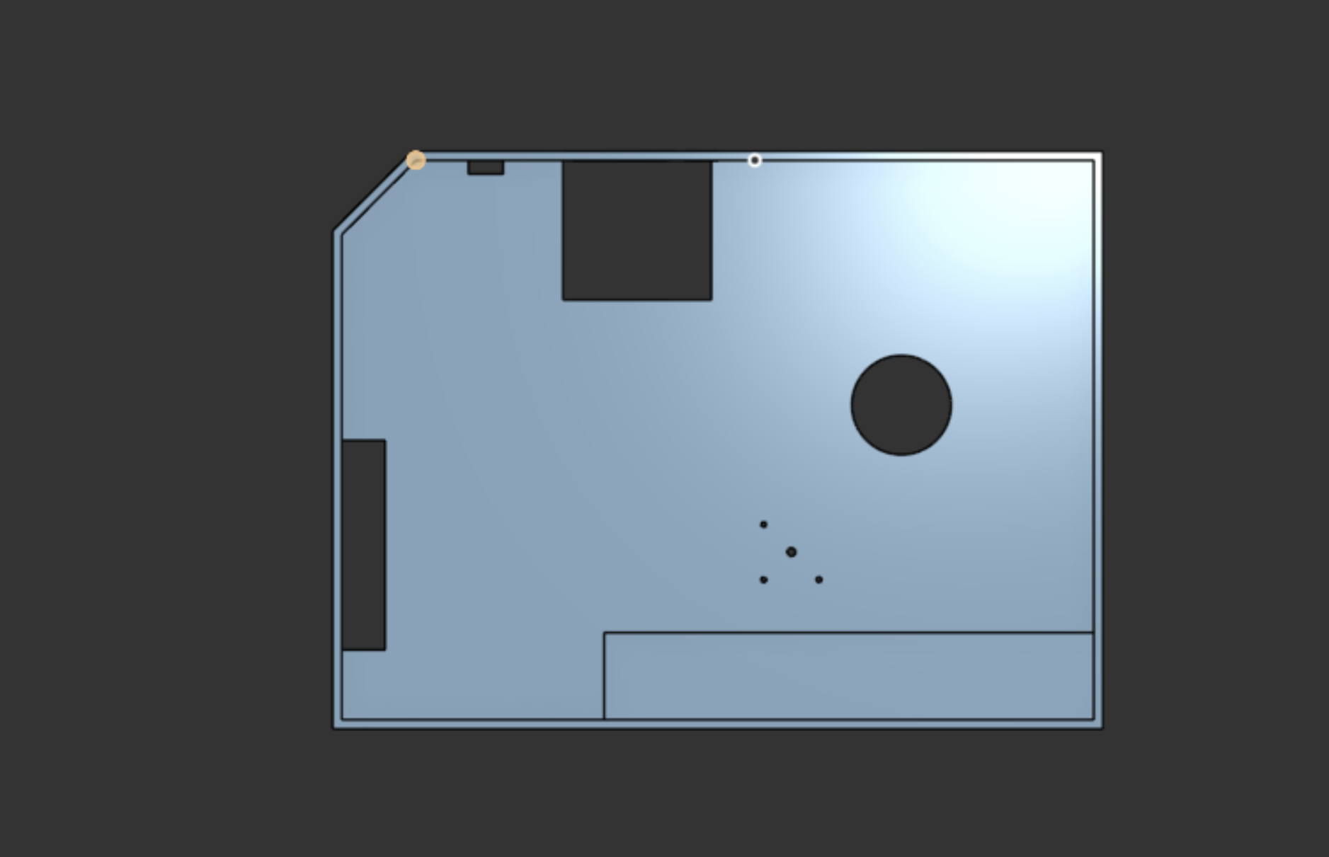
Main Body CAD V2
Last time I worked on main body CAD I designed it so the shredder would be powered by a 775 motor but since that doesn't work I had to change the CAD to fit a drill motor and gear box. This was very hard to do as I basicaly has to start over and because I don't have the drill I bought yet I had to guess the dimentions so I will probably have to change it again in a few days when I get it. I also added a slot for the power cord and a power switch in the back.
I also have to cut out vent holes for the fan and do some more stuff, but I am taking a break from CAD for a bit
Arnav Purbiya
added to the journal ago
Test Code RAMPS 1.4
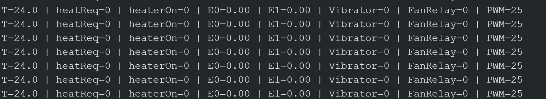
Since I had most of the extruder parts wired up I started writing the code for the arduino mega and the RAMPS 1.4 board. I had to look at a lot of documentation and it took me a while to get all the pin numbers and some context on how to use this board. For right now all the code dose is heat up the extruder to 300 deg C and run the fans but I realized when I plug the 5v fans into the 5v on the ramps it messes with the temp data so I think I am going to have to power them seperatly and have a relay or something similar.
The code also prints out the temp so I can see it while testing. I also tested is the motor spins which it does but I turned it off to test the heating. I am going to add a button and rotary encoder later to control speed and tuff
I also had to de solder a diode on the board in order to power it. This took a really long time as the board is so packed that I didn't want to burn any of the other components around the diode
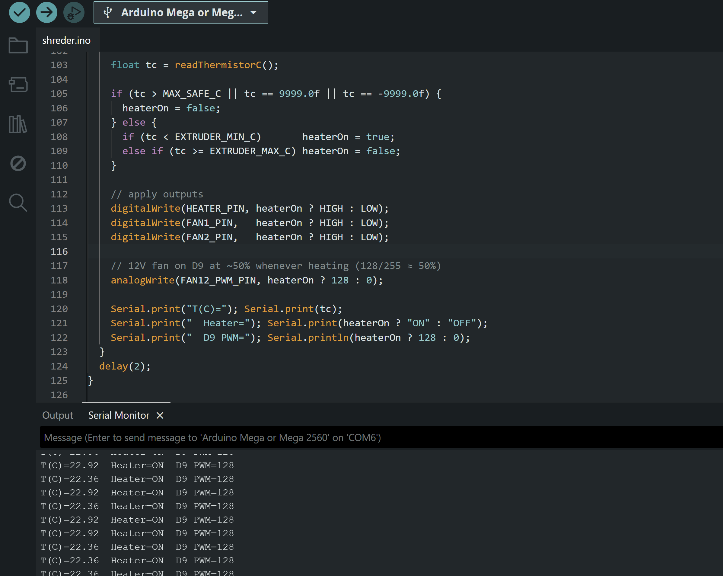
The code is on the github with better formating :)
`
// ----- RAMPS E0 stepper pins (kept, but motor won't spin) -----
#define ASTEPPIN 54 // E0 STEP
#define ADIRPIN 55 // E0 DIR
#define AENABLEPIN 38 // E0 ENABLE
// ----- Heater & sensor -----
#define HEATERPIN 10 // D10 = E0 heater MOSFET gate on RAMPS
#define THERMISTORPIN A13 // RAMPS T0 (your probe -> GND + A13)
// ----- Fans (must drive via MOSFET/transistor!) -----
#define FAN1PIN 4 // your 5V fan #1 (via small MOSFET)
#define FAN2PIN 5 // your 5V fan #2 (via small MOSFET)
#define FAN12PWMPIN 9 // RAMPS D9 12V fan MOSFET (PWM-capable)
// ----- Temp window (edit these) -----
float EXTRUDERMINC = 250.0f; // start heating below this
float EXTRUDERMAXC = 280.0f; // stop heating at/above this
// ----- Thermistor model (100k NTC, B=3950, 4.7k pull-up on RAMPS) -----
const float RSERIES = 4700.0f;
const float R0 = 100000.0f;
const float T0K = 273.15f + 25.0f;
const float BETA = 3950.0f;
// ----- Safety limits -----
const float MAXSAFEC = 300.0f;
const unsigned long READINTERVALMS = 200;
// ----- Control flags -----
const bool RUNSTEPPERTEST = false;
// housekeeping
unsigned long lastReadMs = 0;
bool heaterOn = false;
// --- helper: read thermistor (Celsius) using Beta model ---
float readThermistorC() {
int a = analogRead(THERMISTORPIN);
if (a <= 1) return -9999.0f;
if (a >= 1022) return 9999.0f;
float Rt = RSERIES * ( (float)a / (1023.0f - (float)a) );
float invT = (1.0f / T0_K) + (1.0f / BETA) * log(Rt / R0);
float Tk = 1.0f / invT;
return Tk - 273.15f;
}
// --- optional stepper test (kept, not run) ---
void stepperSpinTest() {
digitalWrite(ADIRPIN, HIGH);
for (int i = 0; i < 80000; i++) {
digitalWrite(ASTEPPIN, HIGH); delayMicroseconds(20);
digitalWrite(ASTEPPIN, LOW); delayMicroseconds(20);
}
delay(1000);
digitalWrite(ADIRPIN, LOW);
for (int i = 0; i < 2000; i++) {
digitalWrite(ASTEPPIN, HIGH); delayMicroseconds(500);
digitalWrite(ASTEPPIN, LOW); delayMicroseconds(500);
}
delay(1000);
}
void setup() {
// Stepper pins (kept)
pinMode(ASTEPPIN, OUTPUT);
pinMode(ADIRPIN, OUTPUT);
pinMode(AENABLEPIN, OUTPUT);
digitalWrite(AENABLEPIN, HIGH); // disable driver
// Heater & fans
pinMode(HEATERPIN, OUTPUT);
digitalWrite(HEATERPIN, LOW);
pinMode(FAN1PIN, OUTPUT);
pinMode(FAN2PIN, OUTPUT);
digitalWrite(FAN1PIN, LOW);
digitalWrite(FAN2PIN, LOW);
pinMode(FAN12PWMPIN, OUTPUT);
analogWrite(FAN12PWMPIN, 0); // off at start
// Thermistor
analogReference(DEFAULT);
delay(50);
lastReadMs = millis();
Serial.begin(115200);
Serial.println("Extruder heater + fans test ready.");
}
void loop() {
if (RUNSTEPPERTEST) {
digitalWrite(AENABLEPIN, LOW);
stepperSpinTest();
} else {
digitalWrite(AENABLEPIN, HIGH);
}
unsigned long now = millis();
if (now - lastReadMs >= READINTERVALMS) {
lastReadMs = now;
float tc = readThermistorC();

if (tc > MAX_SAFE_C || tc == 9999.0f || tc == -9999.0f) {
  heaterOn = false;
} else {
  if (tc < EXTRUDER_MIN_C)       heaterOn = true;
  else if (tc >= EXTRUDER_MAX_C) heaterOn = false;
}

// apply outputs
digitalWrite(HEATER_PIN, heaterOn ? HIGH : LOW);
digitalWrite(FAN1_PIN,   heaterOn ? HIGH : LOW);
digitalWrite(FAN2_PIN,   heaterOn ? HIGH : LOW);

// 12V fan on D9 at ~50% whenever heating (128/255 ≈ 50%)
analogWrite(FAN12_PWM_PIN, heaterOn ? 128 : 0);

Serial.print("T(C)="); Serial.print(tc);
Serial.print("  Heater="); Serial.print(heaterOn ? "ON" : "OFF");
Serial.print("  D9 PWM="); Serial.println(heaterOn ? 128 : 0);
}
delay(2);
}
`
Arnav Purbiya
added to the journal ago
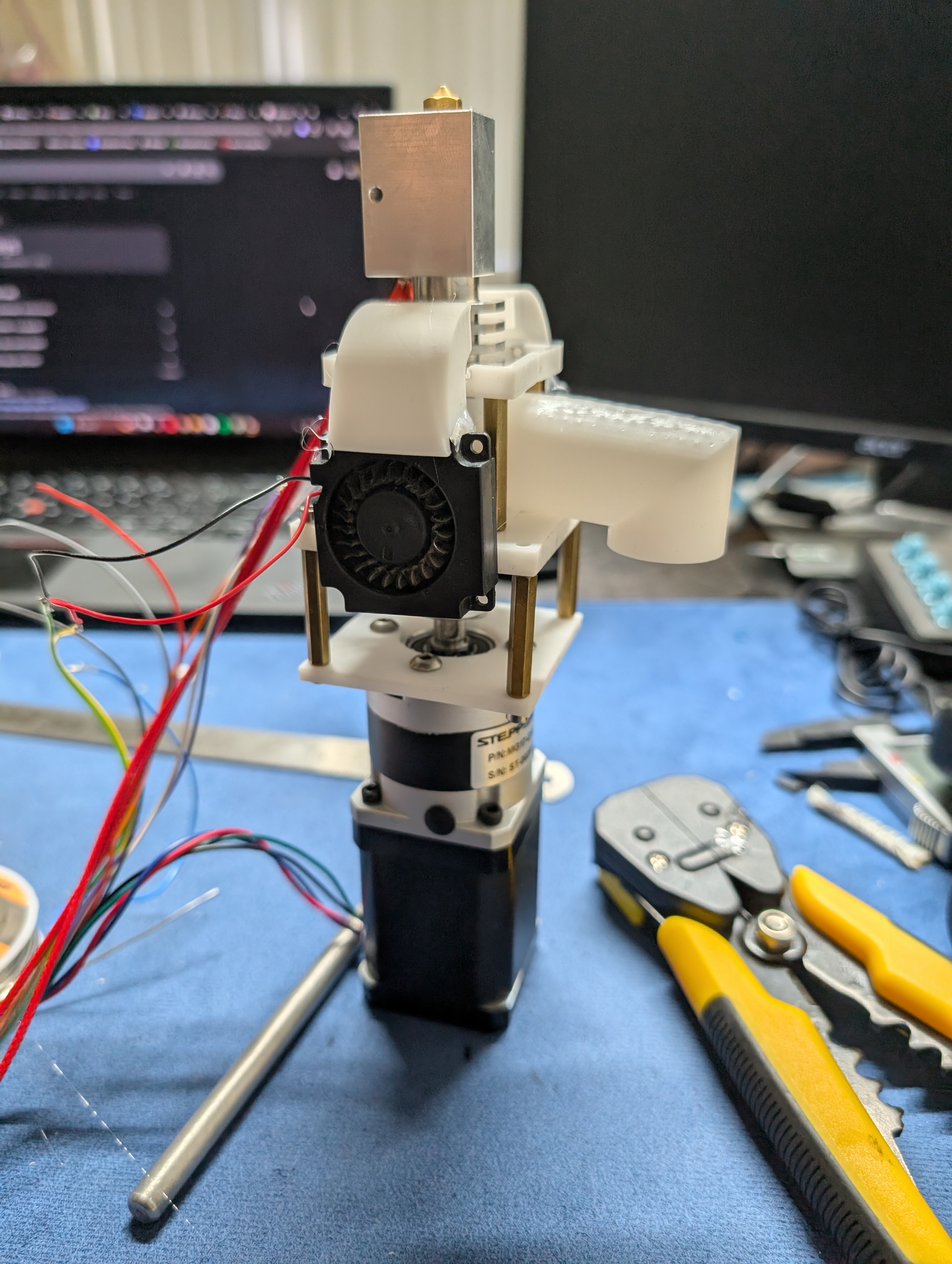
Extruder Assembly
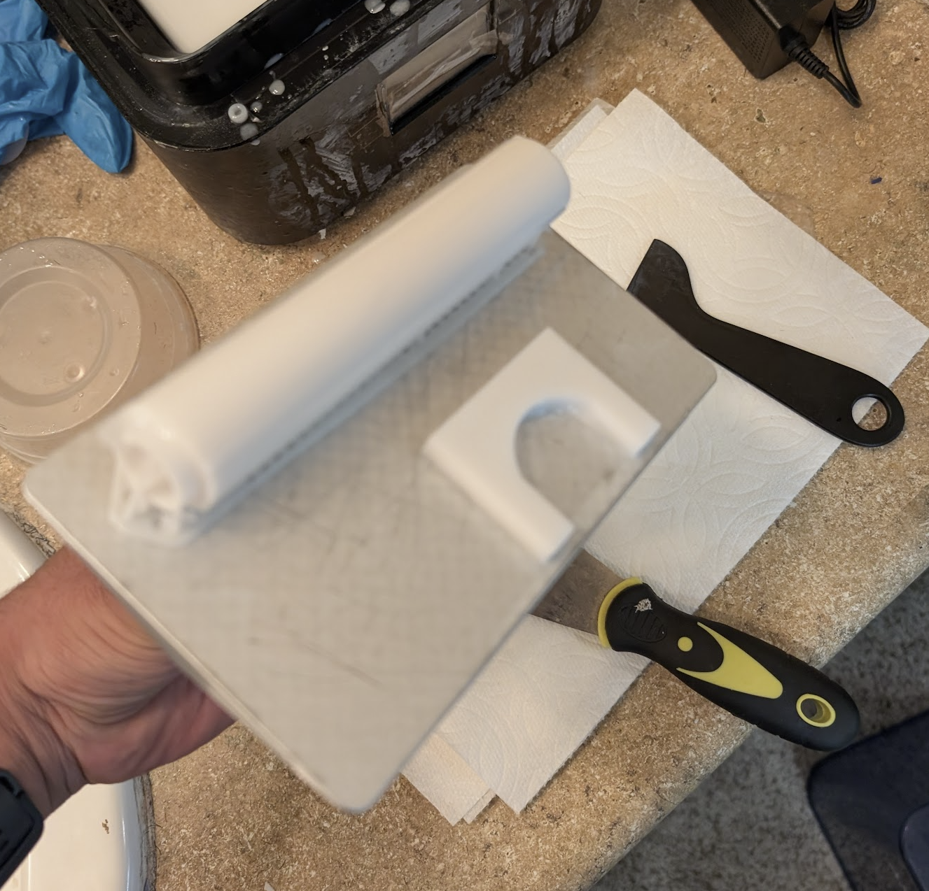
This morning I started of my cleaning all the prints but washing and then curing them
After that I crimped the stepper motor wiers and screwed in the gearbox
And then I got rest of the parts assembeled and then made a wire harness for the fans and the temp sensor, I soldered one side of it and crimped the other side. Dupont is not easy to crimp :(
I glued the fans on and put everything together. I had to do the crimp a few times as I did not get it right the first time.
Now most of the extruder is = together just need to do some cabel management and then test the heating and motor later today

Arnav Purbiya
added to the journal ago
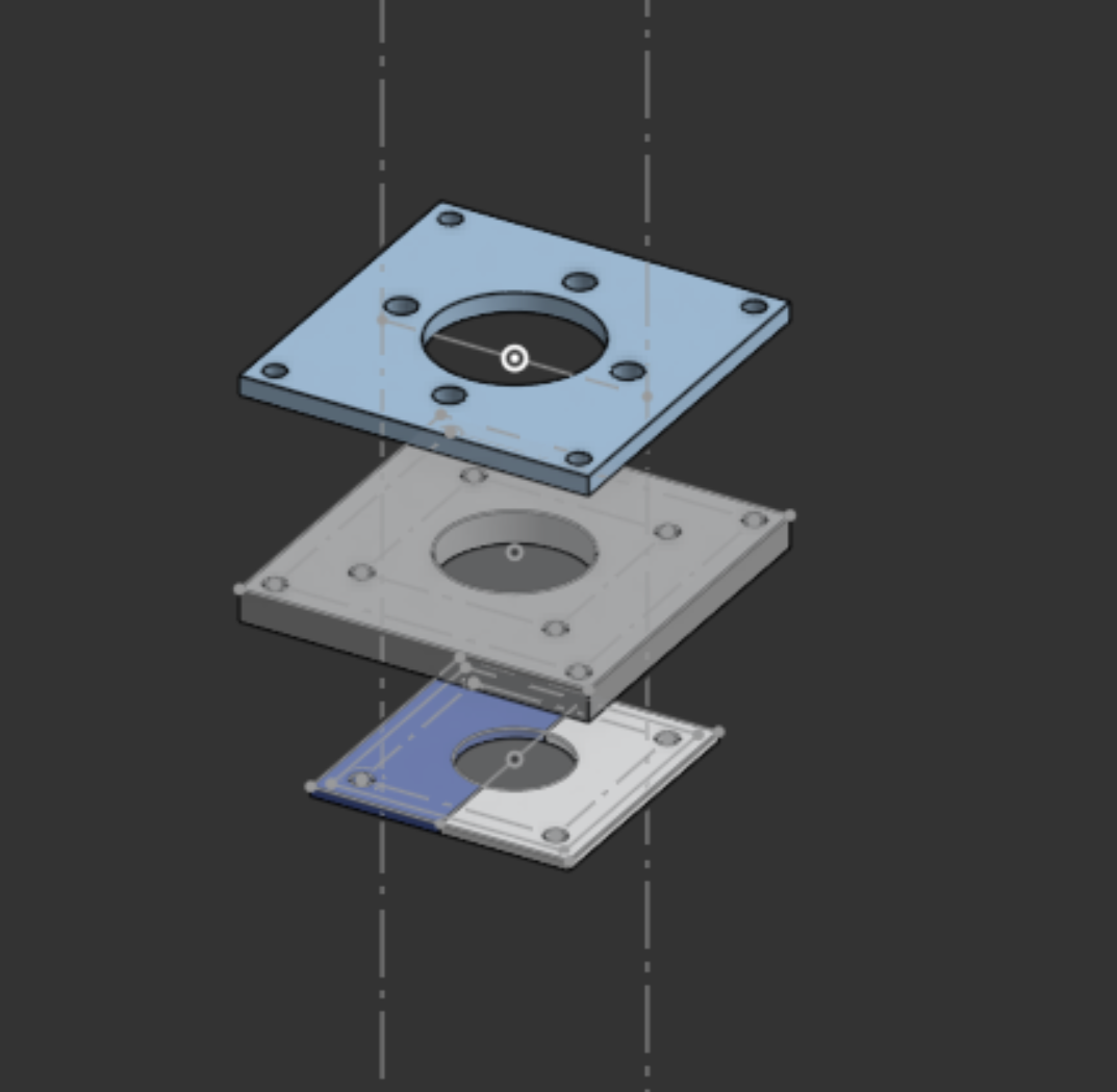
Extruder CAD
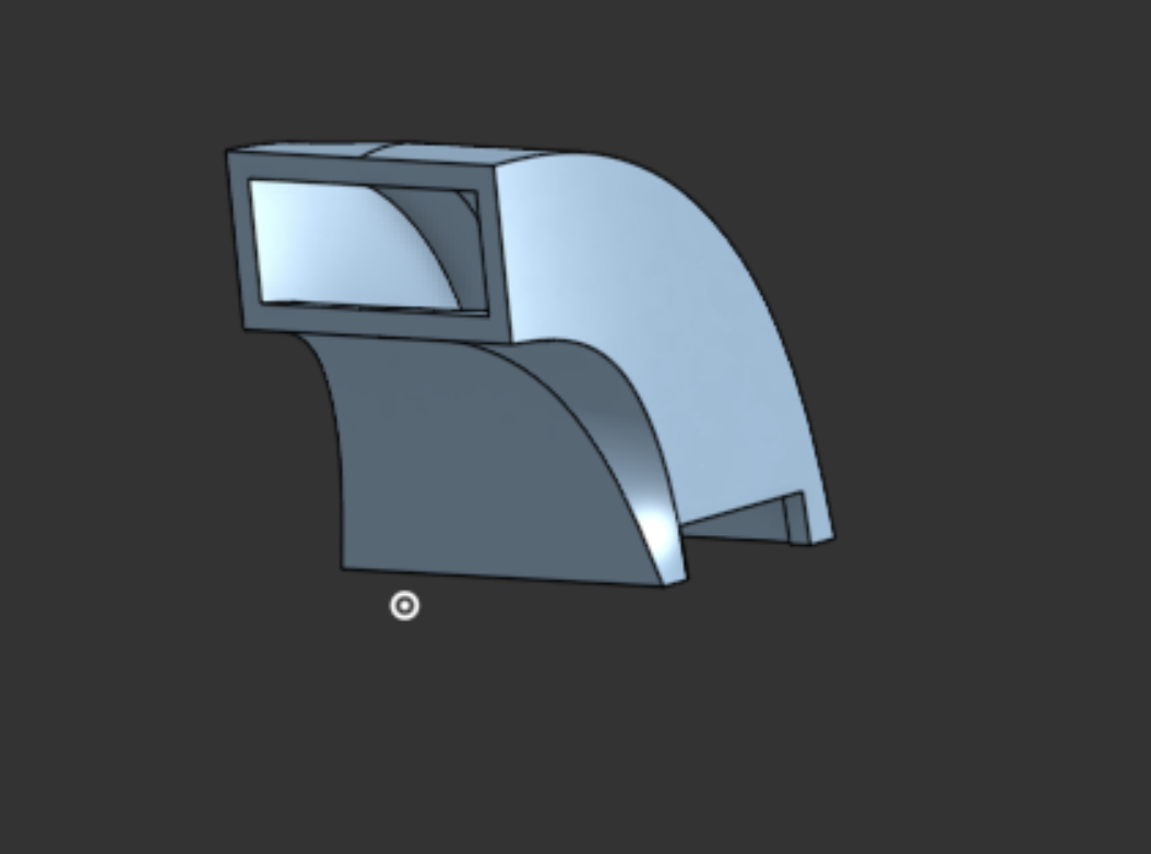
I just worked on the CAD for the extruder, and I know right now it dose not look like much because I did not add the motor or the heat block or pipe. But when I do the assembly tomorrow I promise it will all make sense. I had to model some plates that would screw in with some M3 double pass spacers, a fan duct to aim the air flow where I want it and then the pellet duct to get the pellets to the screw.
This is the stack of plates
This is for the fan
And this if for the pellets
I had a hard time with all the lofts as it was hard to get all the profiles and faces just right. I also sliced it and started the print. I will assembel everything tomorrow morning.
Arnav Purbiya
added to the journal ago
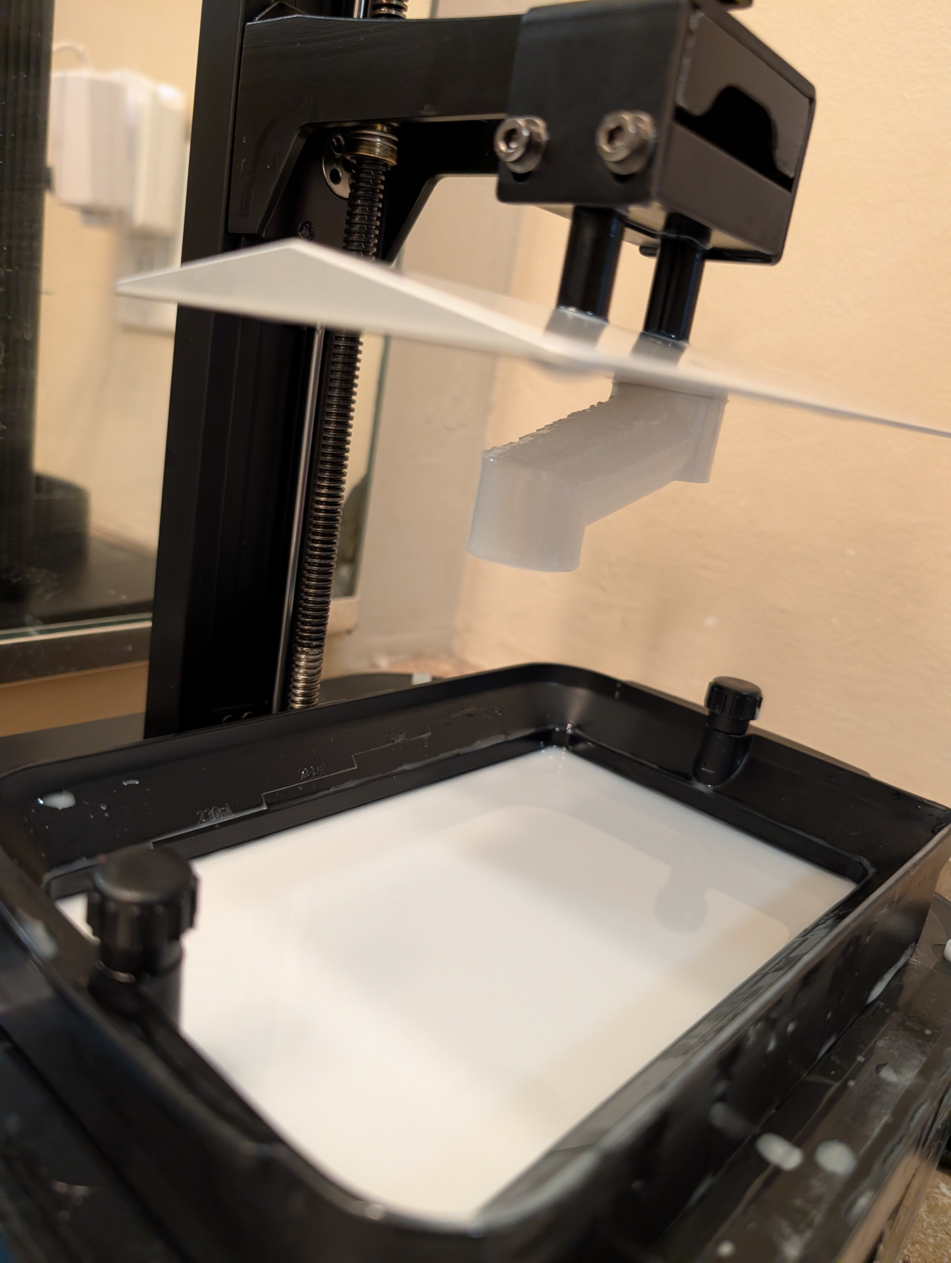
Shredder Assembly
I got the shredder prints all cleaned up and put the assembly together and conencted it to a motor driver to test if this would work. It turns! But when I put poop in there it just stalled under the load. So the 5:1 gear ratio is not going to work going any more that that and the project just gets huge so I found and ordered a cheap 20 buck drill from harbor freight lets see if that works. I put in a some work cleaning the gears as I printed them in resin but it was all for nothing :(
Arnav Purbiya
added to the journal ago
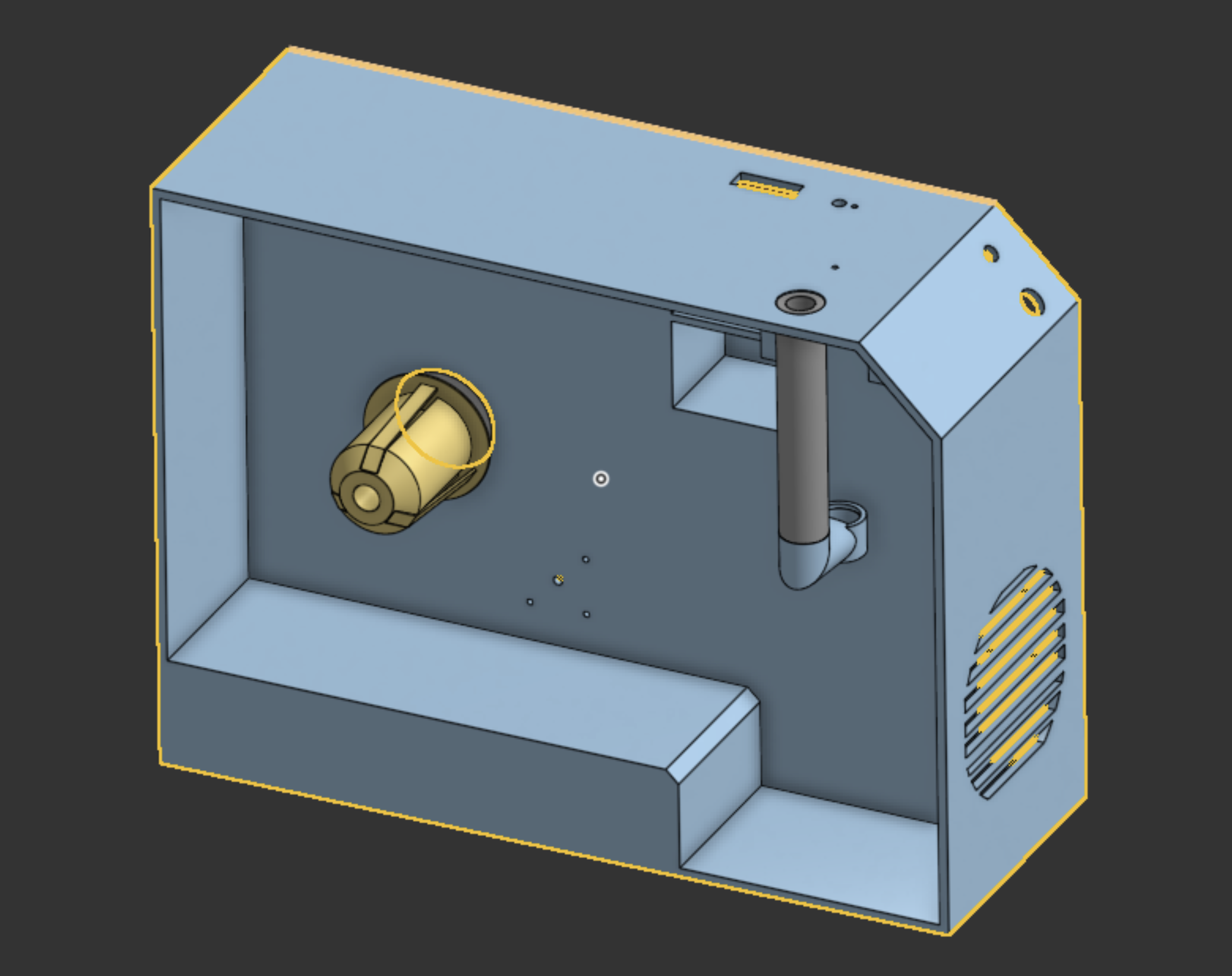
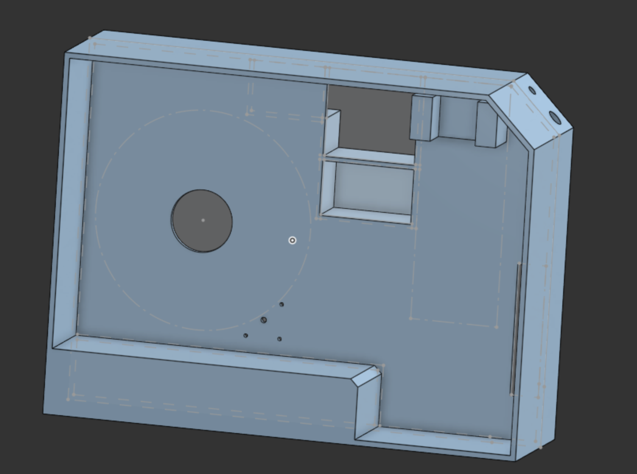
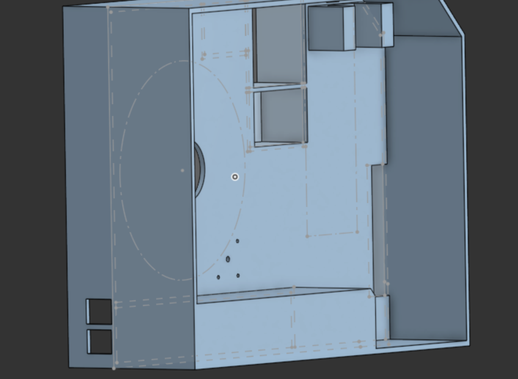
Main Body CAD
I had the sketch from earlier that I used to make this main body, I had to change a few things in order for all the parts to fit. I might have to go back and make more changes as I don't have all the parts and dimentions may not be what they advertize in the images
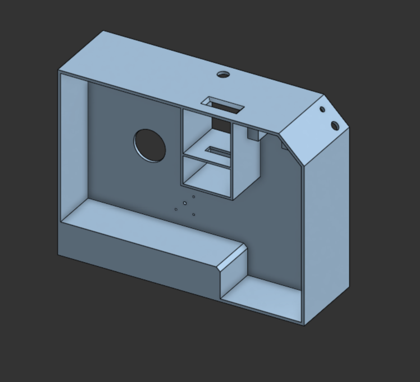
This is what I have so far, I like the overall shape. I had a hard time with some of the component place ments so I just made a masive back place where I can mount the ramps board and other parts
It took a lot of back and forth to get all components to fit in a small form factor.
I also started an assembly where I will be adding all the parts as I design them
Arnav Purbiya
added to the journal ago
Shredder CAD
I started working on the CAD for a shredder, I wanted it to be able to crush down Bambu poop down to a size where it could be run through a pelet extruder. I came accross this model https://www.printables.com/model/738194-micro-plastic-shredder I liked it but it was missing a few things I wanted so I based my model off that one 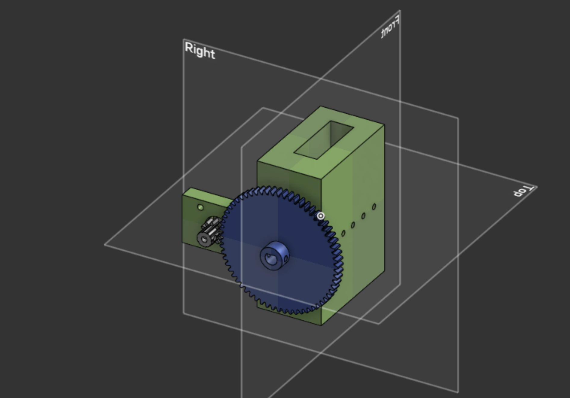 I added a mount for a 775 motor and a 5:1 gear ratio to test it. I was also able to get the model sliced and off to my printers to print. I want to make sure the shredder works before working on the CAD for the main frame just incase I need to try something different, you can find the cad on onshape and I will uplooad the step files on Github as well.
Arnav Purbiya
added to the journal ago
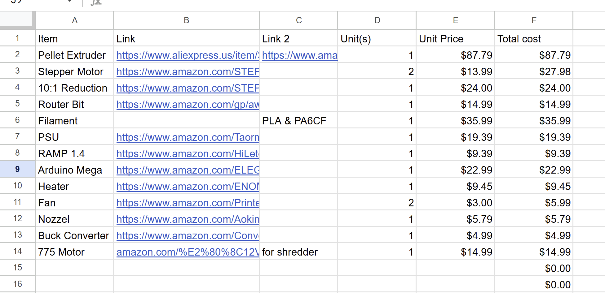
Added Items to BOM
I changed the formatting of the BOM today and added two items that I forgot yeaterday. I ordered the new parts so they should arrive soon as well. The parts I ordered yeaterday should also com ebefore the end of the weekend and that will help me spped up my cad work. I am going to finish the sketch later today. I am not sure if the 775 stepper motor will get the job done but I hope it does, I might have to gear it maybe 5:1 or maybe even more.
Arnav Purbiya
added to the journal ago
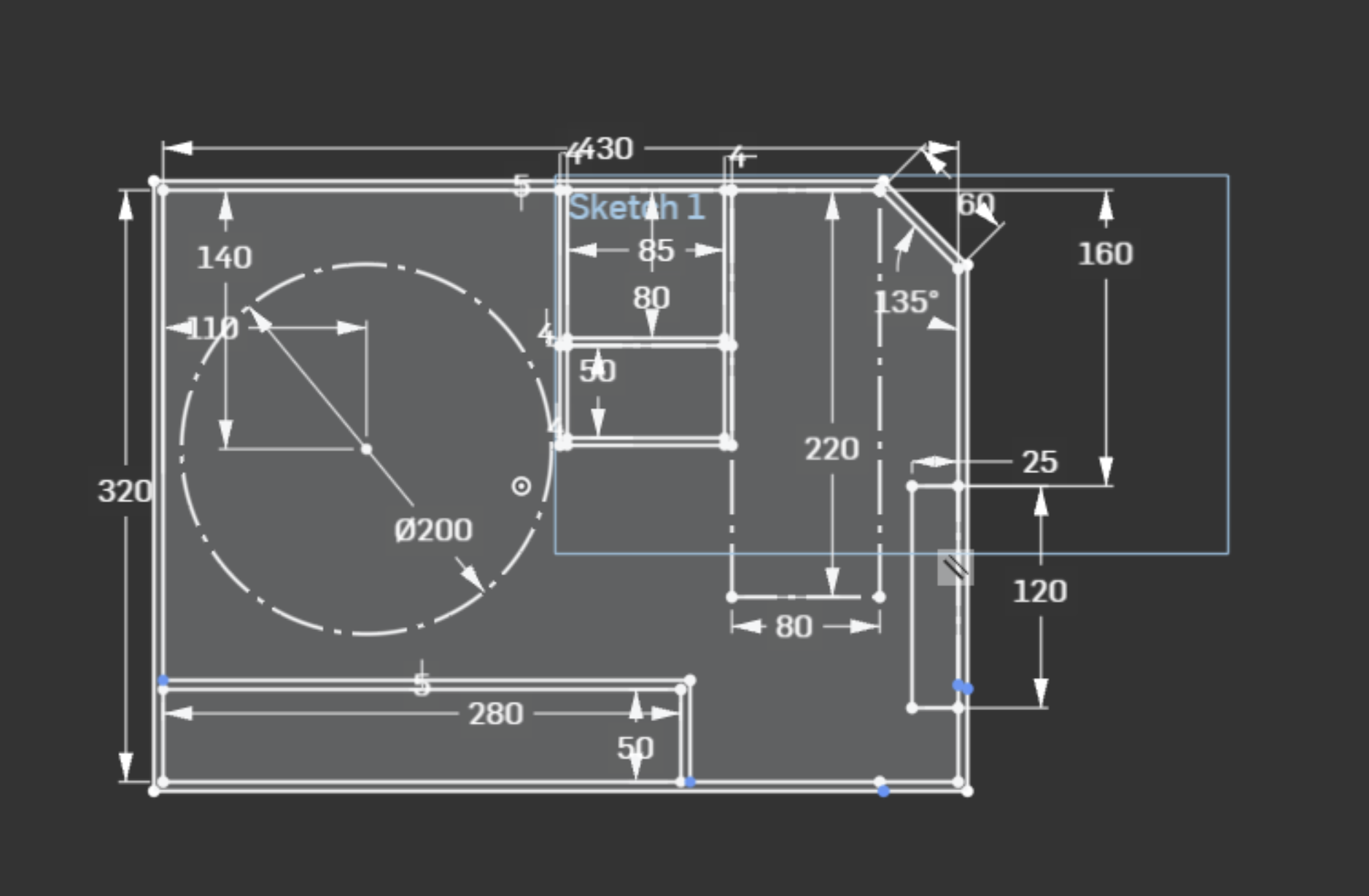
Started Working on CAD Sketch
I hoped into onshape and started working on the CAD sketch, I took what I drew out and then make a rought sketch after which I had to go to many different product pages to get dimentions of the different items I want to use and dimention that in. This all tool a long time because I wanted to dimention everything as accuratly as I can so its easier for me later down the line. The angle on the side is where I would want to mount the button and stuff, still need to figure out how the shredder will work.
Arnav Purbiya
added to the journal ago
Researched Parts & Created a List
I did a lot of research looking to see if anyone had already done something like this before or any parts or components I can find. I did not see anything promising so I created a list of parts I think I will need. I am most likely going to change parts as I get more and more into the project but for now this it it. I also went on printables where I found a pelitizer model which gave me an idea for the shredder and why I have a router bit in my BOM. I already have some of the parts but I have ordered all the other parts and they should come in a a week untill then I am most likly going to work on cad. 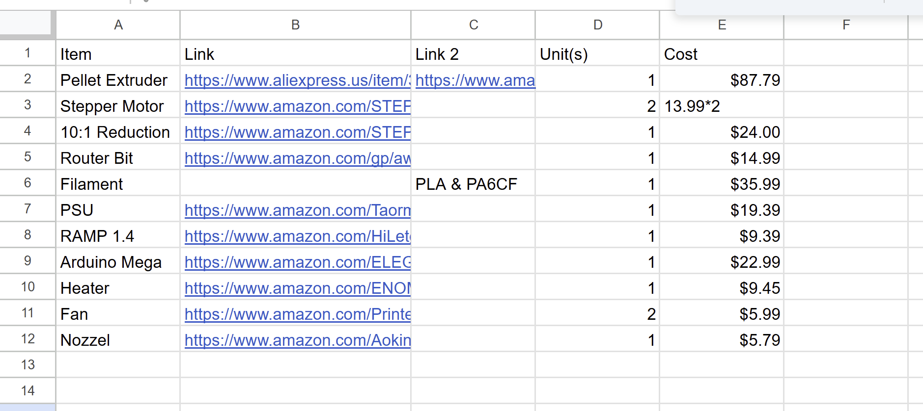
Arnav Purbiya
added to the journal ago
Drawing Rought Sketches
I started brainstroming ideas and sketched out some ideas of how everything can be positioned. I had to think about overall size as I want to keep it kinda small. Next I am going to look of some of the parts and start sketching it in Onshape. I also need to see if a motor can power a mini shreder. I also need to run 2 stepper motors one from extruder and spooler. I am thinking of using the RAMPS 1.4 board. I looked into all the power requierments but I need to find a good power supply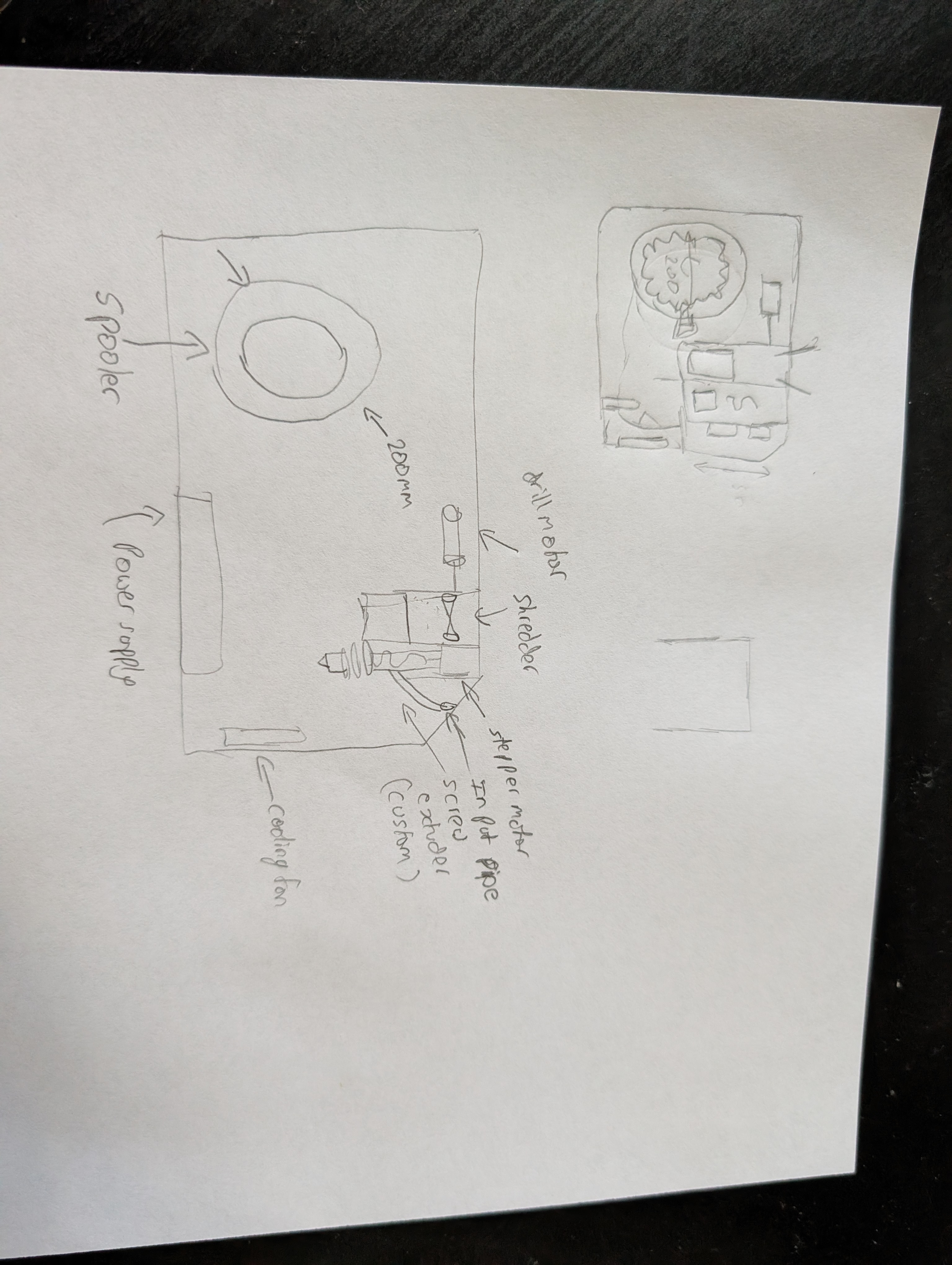
Arnav Purbiya
started Filament Recycler ago